

This series explores each of the numerous slicer settings available in most 3D slicing softwares. Last time we looked at the settings for controlling your extruder. This time we will look at how to control the layer settings for your prints.
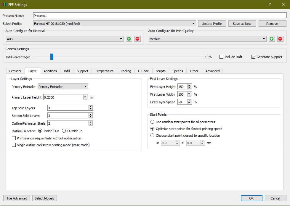
Primary Extruder
This option allows you to pick an extruder from the dropdown and set the layer settings for each extruder individually. Most users only have single extruder printers, so this option is not pertinent. However, if your printer is a dual or triple extruder printer this can be an important setting to achieve customized print settings for the different materials or colors you are working with.
Primary Layer Height
The layer height has a direct relationship to print time and resolution of the print. This setting is one that you will change frequently depending on the circumstances for your print. If the part does not need to be very high resolution, it is always best to put a larger layer height as this will print faster. Layer height and print time pretty much scale linearly, so if a 0.3mm layer height print takes 5 hours, that same print at 0.2mm will take 7.5 hours. However, if you need a higher resolution print and are not concerned about the time, then high resolutions can save post processing time. For most consumer printers the nozzle size is 0.4mm and the upper bound of layer height you should use for a nozzle is 80% the diameter of the nozzle; otherwise, you can build up pressure in the nozzle. So, for most printers the upper range is 0.32mm. There isn’t technically a lower limit based on the nozzle size as this is more determined by the stepper motors on your printer and their resolution. A healthy lower limit would be 0.5mm, but even still most people do not go below 0.1mm.
Top Solid Layers
The amount of top solid layers can have a large impact on surface quality for the print. This setting tells the printer where to stop printing infill and start printing solid layers again close off the print. A pretty common value is 4 layers. This means at any top surface point there are four completely solid layers below that point. This can help improve strength and also improve quality. If you are printing a part with low infill, you will probably need to increase the amount of top layers to save material and print time. The reason for this is because the spacing between infill is now larger and will require further bridging over the space between the infill. This can lead to sagging. The more top layers you have, the more likely this is to be corrected as you start building a solid foundation underneath the current top layer with the previous top layer. If you are printing with low infill and are seeing small voids in the top, this may be an easy solution. The more top layers you add though, the longer the print time will be because you are replacing infill layers with solid layers which take significantly longer to print.
Bottom Solid Layers
Bottom solid layers are similar to the foundation of a house. They build a strong solid surface for the rest of the print to build upon. This number tells the printer at what point to stop printing solid layers and start printing infill. A typical value is 3 layers. You may notice that this is lower than the top solid layers. This is because the material is being printed on a nice flat bed, so there is no concern for dropping or voiding like the top layers might see.
Outline Perimeter Shells
As we have covered the top and bottom of the print, this setting controls the side or walls of the print. It basically determines how thick the part is everywhere besides the top and the bottom. A good value here is 2 walls for a 0.4mm nozzle. This provides great strength while still keeping print time to a minimum. If you are using a different size nozzle, you may be able to get away with less or more walls as the lines become thicker or thinner.
Outline Direction
This option selects whether the wall layers start from the inside wall and work out or whether they start on the outside visible layer and work their way in as the print goes. Most of the time it is best to leave this setting as inside-out. This allows for any small print problems that may occur from retraction or something else to be fixed on the inside layers that are not visible to people while keeping the outside layers nice and clean. Also, inside-out is good for parts with steep overhangs as it gives more surface for the material to grab on overhangs.
Print Islands Sequentially Without Optimization
“Islands” in 3D printing describe parts of a print not connected to anything else in the x-y plane for a given layer. Basically, this means that if the extruder has to travel from one spot to another without laying material on a given layer that it is travelling between two different islands. If the print islands sequentially without optimization setting turned off, the printer will optimize the print for time and speed by reducing the number of travels between parts. This usually leads to the printer printing a layer and then immediately printing another layer on top of that for the same island. Then, it travels rather than traveling between the two islands every time, essentially reducing the travels to half. This works fine if the islands are large and gives the material enough time to cool down. However, if you are printing small islands, the printer can immediately start printing a layer on top of material that has not been given the opportunity to cool down completely. This can cause the material to burn, melt, result in blobs, scorch marks, etc. By selecting this option, you can force the printer to switch between islands giving each island proper time to cool down before printing the next layer on top of it.
Single Outline Corkscrew Printing Mode (Vase Mode)
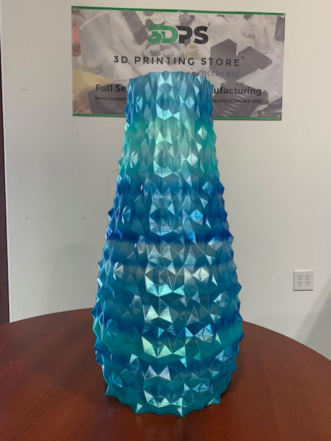
This option is for parts that only need a single continuous wall. Essentially, the extruder extrudes throughout the entire print slowly– building on top of previous layers without ever needing to retract or travel. This saves considerable amounts of time. However, it is only usable in very specific settings. If your part has any islands or requires more than a single wall for strength, this setting cannot be used successfully. As the name implies, it is very useful for vases or any single body container.
First Layer Height
The first layer is often the most crucial setting for any print. Most of the time, if the first layer comes out correctly, then the rest of the print will be successful as well. In order to try and ensure proper adhesion, it is possible to change the settings for the first layer. One of these settings is the first layer height. The first layer height will increase or decrease the vertical thickness of the first layer by the specified percentage. We recommend using a slight increase such as 120% to help improve any slight defects in the build plate such as scratches or chips. It also creates more surface area to improve adhesion.
First Layer Width
The first layer width adjusts how thick the first layer is going to be. This can help with first layer adhesion to the bed. When it is increased, it increases the surface area. Using small nozzles can benefit from this setting being increased. However, increasing this too much can create an “elephant’s foot” on the print. An elephant’s foot is when there is excess material on the first layers from material being over-extruded.
First Layer Speed
This dictates how quickly the extruder moves during the first layer of printing. Reducing the print speed for the first layer can reduce the chance of any imperfections during printing of the first layer. This will provide better adhesion and a solid base layer for the rest of your print to be built upon. We recommend running this somewhere between 70% to 100%.
Start Points
There are three options for this setting. Each can be useful depending on your project requirements.
“Use random start points for all perimeters” does exactly what it says. For every perimeter, or wall, the slicer selects a random point on the perimeter to start extruding. A little excess material can create a small blob at the beginning of a perimeter; under-extrusion can occur leaving a small void and this leaves small noticeable imperfections on the print. If the starting points are randomized, these slight imperfections can be less noticeable.
“Optimize start points for fastest printing speed” allows for faster print times by reducing the amount of travels or the travel distance. This can also create problems though by creating a seam that runs vertically along the part; often the fastest place to start a new layer is where the previous layer ended. This can apply extra heat and/or material to the previous layers endpoint which creates burns or blobs; when this is done over the entire print for every layer or most layers, it can create a vertical line that is visually different along the part.
“Choose start point closest to specific location” allows you to input an x and y coordinate; then, every layer will be analyzed where the closest point on the part is relative to the coordinate pair. This can be useful if you have a face or surface that will be hidden or is less visible. If so, you can orient the part to face a given coordinate and set the start point at that coordinate. This will hide any imperfections from start points in a less visible area.
If you want to get your printer working optimally, contact us at project@the3dprintingstore.com or call at +1 720-443-3733