
Originally written by Michal Swoboda for ZMorph
Electronic circuits are almost everywhere nowadays. They are on your wrist and in your pocket, they hide in your car, and even are present in space! Therefore there is a growing number of electronic enthusiast who wants to fulfill their creativity using knowledge and proper tools for making the most outstanding things they can imagine! But how circuit boards are made?
Different Types of Circuit Boards
For most it’s all starts with the idea schematic – a kind of how it works graph, that uses proper symbols for resistors, capacitors and so on.
Then it’s time for making your idea come to life. Well, there are few ways you can achieve that. Let’s start from the bottom.
You could just solder parts together using their terminals and some wire to get a messy spaghetti connected in mid-air like some sort of monster (that could still work).
Secondly, you can use breadboard that’s easy to modify and doesn’t require soldering but suffers from its fragileness. It’s easy to disconnect something and it’s often really big, and as it gets bigger, often get messier.
Next thing you can do is use a “universal board” that’s similar to a breadboard but requires soldering, which makes it more reliable if you want to utilize your circuit. The downside of this kind of board is the fact that you need to connect all the elements using wires. The bigger the circuit is the more wire is needed, and this leads to a lot of work needed to complete a circuit
Last but not least, we’ve got so-called Printed Circuit Boards or PCB for short. What’s that and why it’s the essence of all electronic circuits?
What is a PCB?
PCBs are boards that are dedicated to one special circuit that you have created, the biggest upside of such boards is the fact that they are extremely reliable, can be fitted in your design perfectly (enclosure, chassis, etc.), and lastly you can use Surface Mounted Devices (SMD) that can shrink the whole circuit a lot!
However, how do you make it? Making circuits nowadays is done using a Computer Aided Design (CAD) software, there’s are a lot of programs to choose from but I personally strongly recommend KiCAD. Using your idea schematic, you lay down tracks between components’ terminals and defining your board shape, usually, it’s a rectangle but with PCBs, you can go with lots of shapes like circles, triangles, rings, stars, banana? Why not!
Making a Custom PCB
You’re done designing an electronic circuit, but you would like to have a physical board. So how do you do it? Again, you’re not limited to just one solution. You can use various DIY methods to do this (like the Iron method), this way you can have your PCB ready at the same day, but these methods often lead to multiple tries to get a good result. It really might be frustrating. And there’s a big chance that the thinner the track the more likely it is that it won’t be properly created.
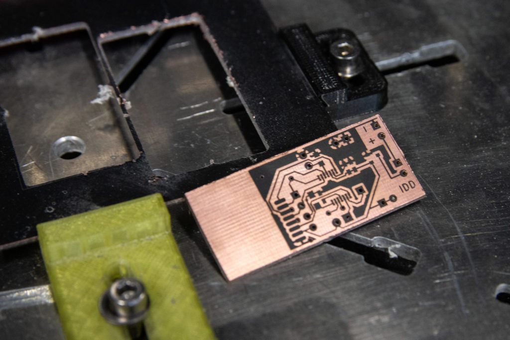
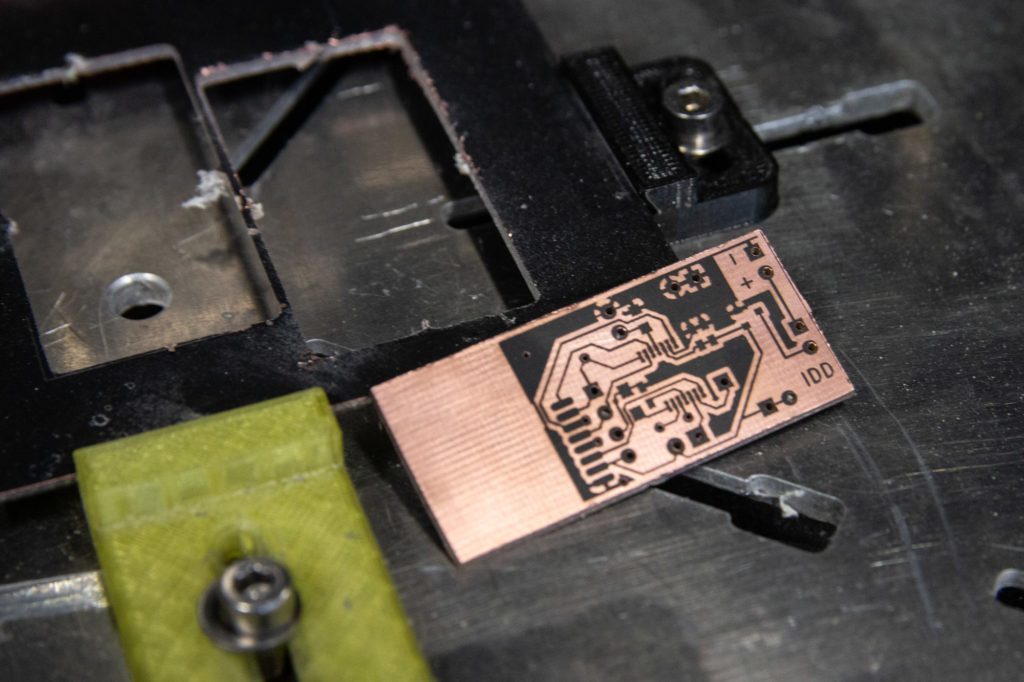
Custom PCB made on ZMorph VX
ZMorph VX and PCB Making
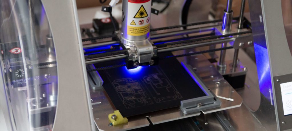
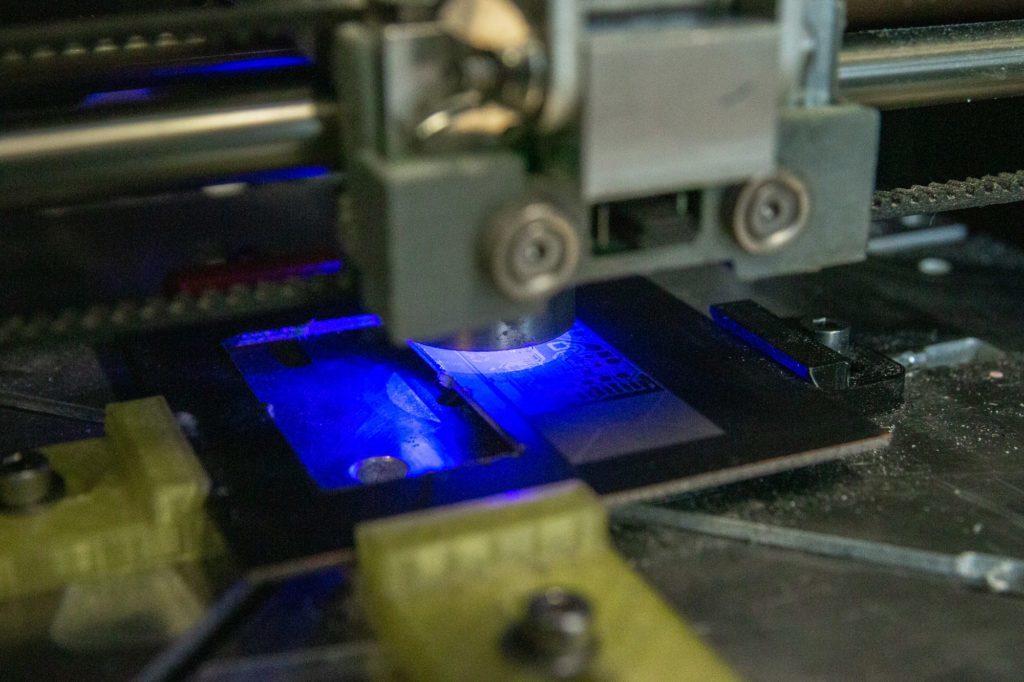
So are there other methods? Of course there are. You can utilize the versatile ZMorph VX for a rapid manufacture of your own Printed Circuit Board. For some of You readers, you’re familiar with milling PCB tracks using spindles. But here at ZMorph, we’ve taken a different approach. Because of multiple toolheads, we asked ourselves a question. How would the laser work, for creating tracks? There is a way to make a custom PCB with the Laser PRO toolhead and we came across a simple solution.
Making a custom PCB on ZMorph VX
Let’s cover an ordinary FR-4 copper laminate with a thin layer of ordinary matte black spray paint. That way laser beam evaporates paint leading to the revelation of copper. The laser method is easy to use, we just need to set toolhead to a proper height, which doesn’t need to be precisely trimmed. That way we can obtain a laser beam of diameter approximately 0.12 mm.
According to simple math, if our laser beam is that thin, theoretically we can achieve spacing between tracks of 5 mils. This is really tiny! And almost impossible to get in other DIY methods.
After creating laser tracks, we can switch to CNC PRO toolhead, do a little positioning check and then drill holes and mill cutout of our board. There still exist some nasty leftovers from paint evaporation process, but using a pencil rubber nice and easily gets rid of that.
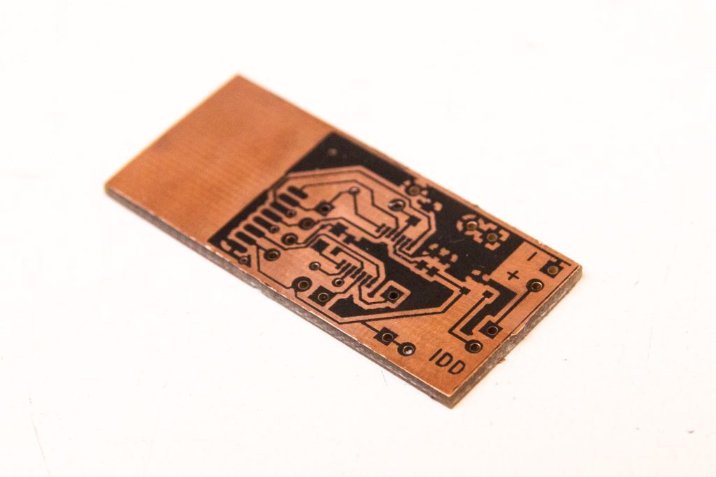
Now PCB is almost ready, we just need to bathe it in the etching solution. Thanks to prior rubbering, the chemical reaction between copper and solution should be fast. All the revealed copper should be etched from the board. There’s only one last step you need to take. Clean up the spray paint with some solvent. Here you go! You’ve got yourself a PCB that’s ready for soldering.
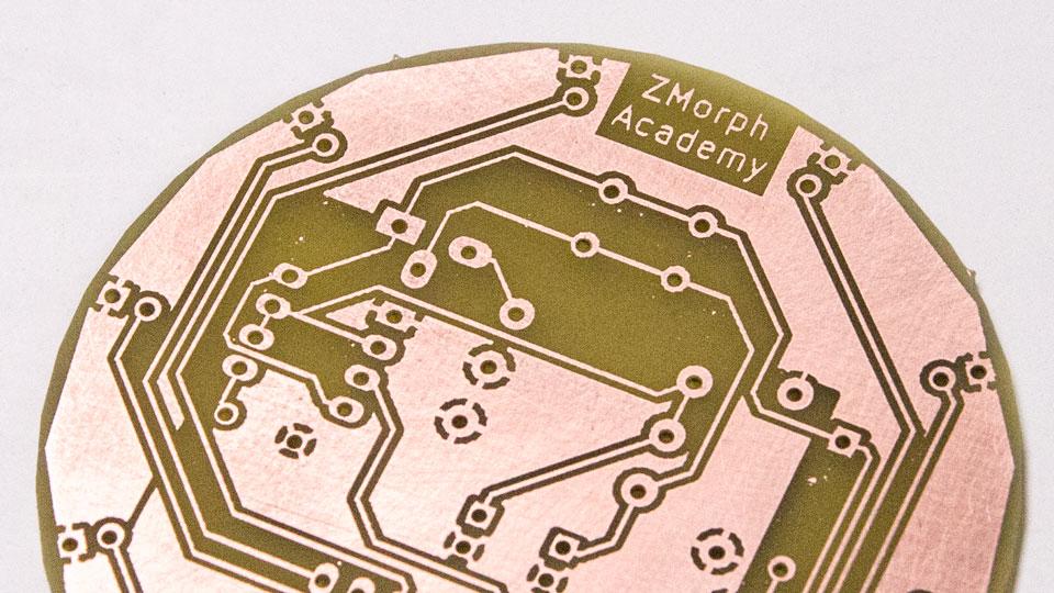
Custom PCB made on ZMorph VX
How long that it took? 2-4 hours? And for more than 80% of the time the things were done by itself! Time factor of this solution is outstanding, that’s why most of electronics prototypes that our R&D department creates are done on ZMorph VX.
If you want to get better knowledge about all processes and learn how to make a PCB using ZMorph VX, please visit the Advanced Course at ZMorph Academy.

Michał Swoboda is an engineer and Embedded System Developer at ZMorph. He works at R&D department and is constantly testing new products and working on different electronics.