
TinkerCAD is a free browser based software developed by Autodesk to inspire more people to start creating. It teaches the fundamental concepts of how things are designed in a simple way that anyone can understand. Within a few minutes, people can begin creating their ideas.
- Go to Tinkercad.com
- Create an account if you don’t already have one by clicking “ Join Now” in the upper right hand corner
- In the websites dashboard click “Create new design”
- This next area is called your workplane; its where all the modeling takes place
Getting to know TinkerCAD
- There are a few basic tools that TinkerCAD offers.
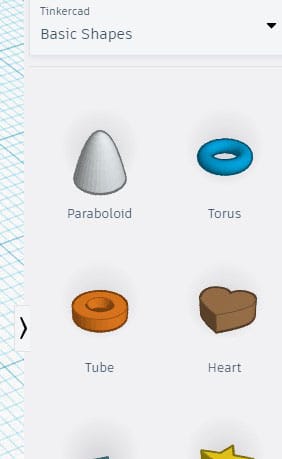
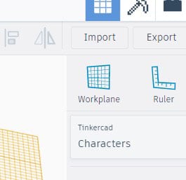
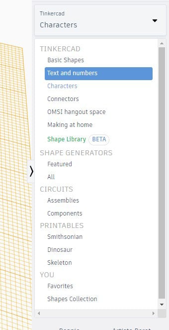
- If you look on the right side of the screen, you will see a drop down menu that offers pre-configured shapes and models. These range from basic shapes to different types of part connectors. Take a few minutes and click through the different options in the menu to learn about the different facets that TinkerCAD offers. I’ll refer to this menu as the Model Menu through these instructions.
- Above the Model Menu, there are three tools:
- Workplane – sets the work plane to a surface you select.
- Ruler – allows you to measure your model as well as get a perspective for its size.
- Notes – allows you to place an annotation about a feature or part of the model anywhere in the workplane.
- In the top right of the screen next to your account icon, there are 3 more options:
- 3D Design – this is defaulted and where you will primarily be working.
- Blocks – this converts your model to a style that resembles the popular game “Minecraft.” This option gives you basic parameters to edit.
- Bricks – this converts your model to individual bricks like Legos for assembly. This also gives you basic parameters to set such as brick size, etc.
- Below these icons is where you can import an existing model, export your current mode, or send your model via email, etc.
- On the top left of the screen you will notice a box that has labels on it such as “top,” “front,” etc. This is how you select different views of the work plane. You can rotate the views by holding the right mouse button or use this box for parallel views.
- Above the view changer box there are two arrows. These are “undo” and “redo.” This allows you to go back in time if you want to remove a feature you recently added and vice versa.
- To the left of these arrows are 4 icons: “copy,” “paste,” “duplicate/repeat,” and “delete.”
- In the top left, to the right of the TinkerCAD logo, there is a menu that allows you to view and visit previous projects. This is also where you can start a new design by clicking “New Design.”
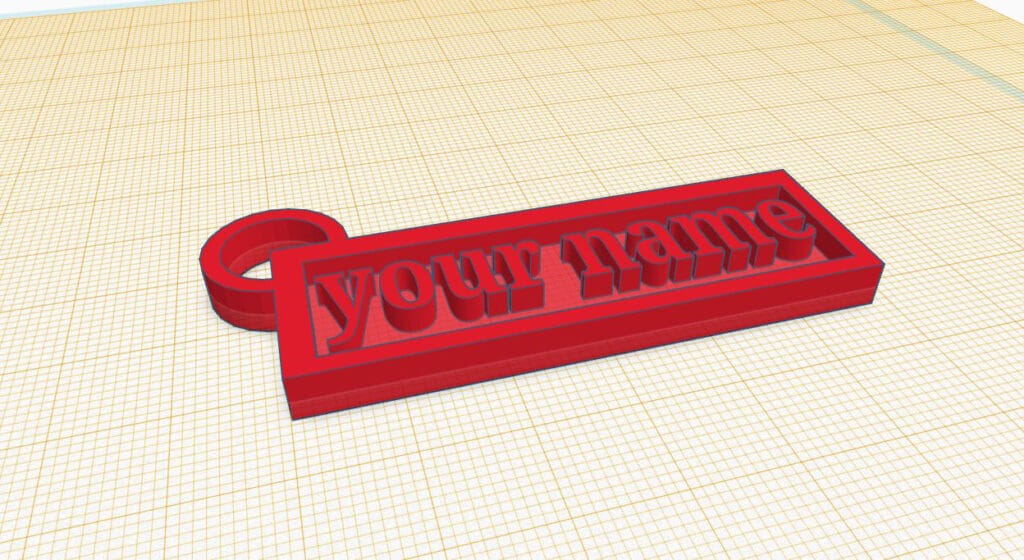
Design Tutorial: Personalized Keychain
This tutorial will show you how to create a personalized keychain with anyone’s name. At the same time, we will cover TinkerCAD basics as well as modeling for printing aspects.
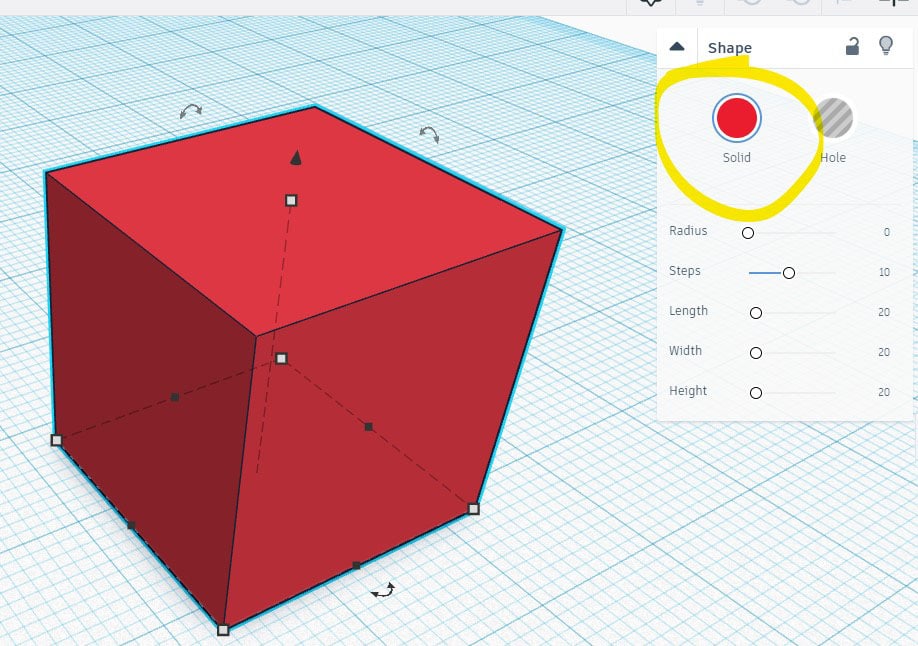
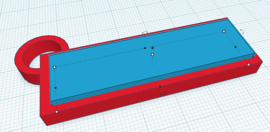
1. In the basic shapes tab on the right side under the Model Menu, drag and drop a box into the work space. Make sure solid is selected and not hole in the shape menu on the right.
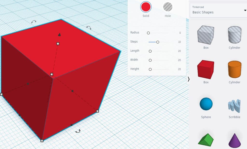
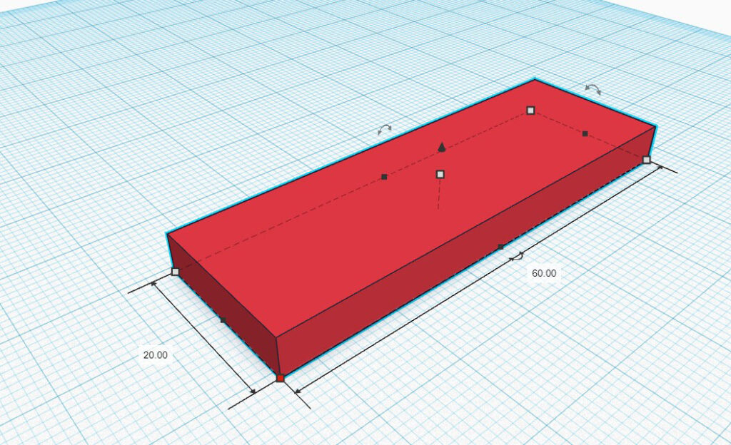
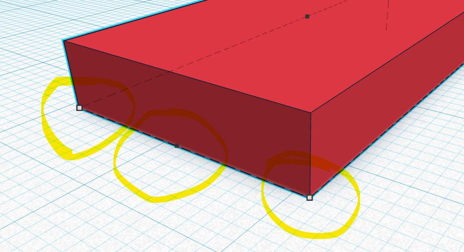
2. Dimension the box as you see fit using the grey or black squares that are on the model when you click on it. For my keychain, I used 20mm by 60mm and 5mm tall.
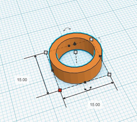
3. Next add a tube from the Model Menu under basic shapes as well. Dimension this as you see fit. I used 5mm tall and 15mm by 15mm.
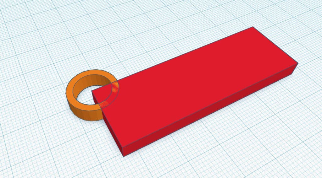
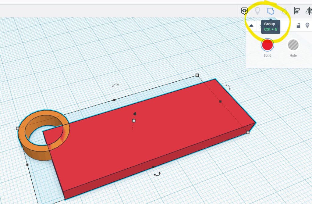
4. Move the tube so that it intersects one of the corners on the box. Select both using either shift click or click and drag a box over both. Select the group in the top right. This will combine both parts.
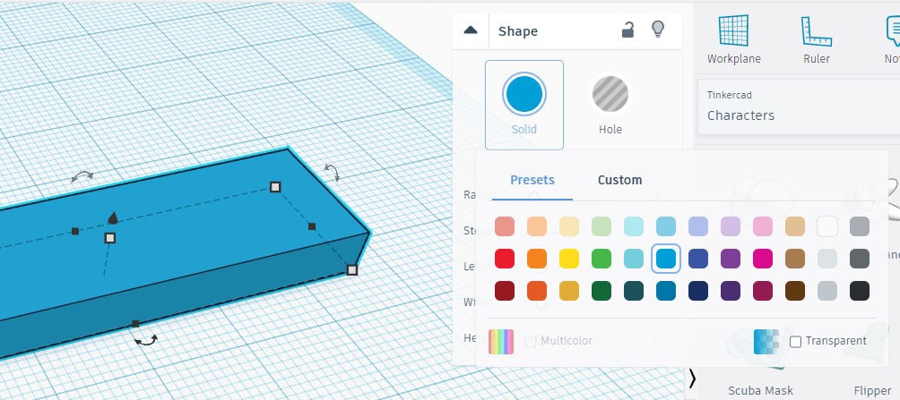
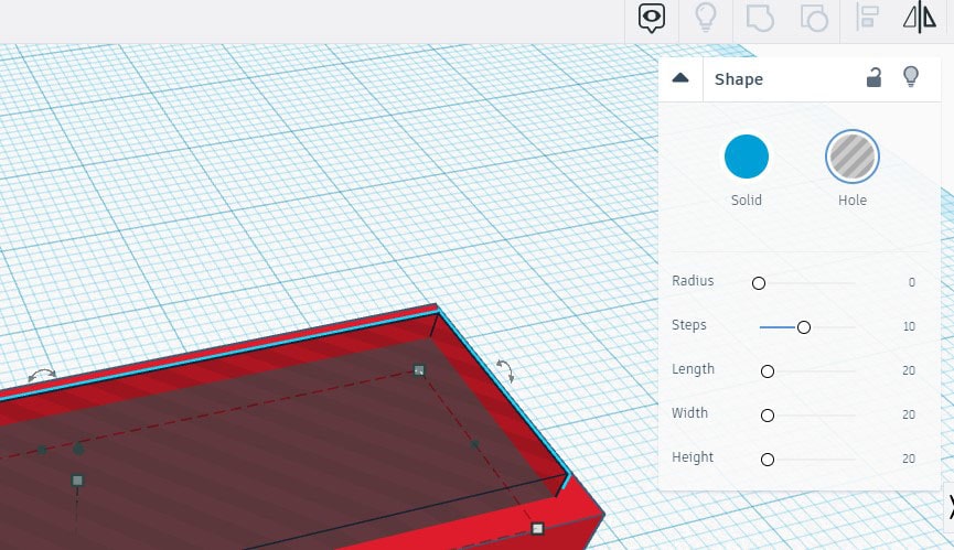
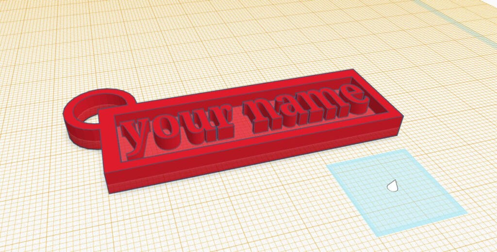
5. Next, we’ll add a space for our name. Drag and drop another box from the Model Menu. It is recommended to make this box a different color by clicking the solid option in the shape menu on the right after selecting the model.
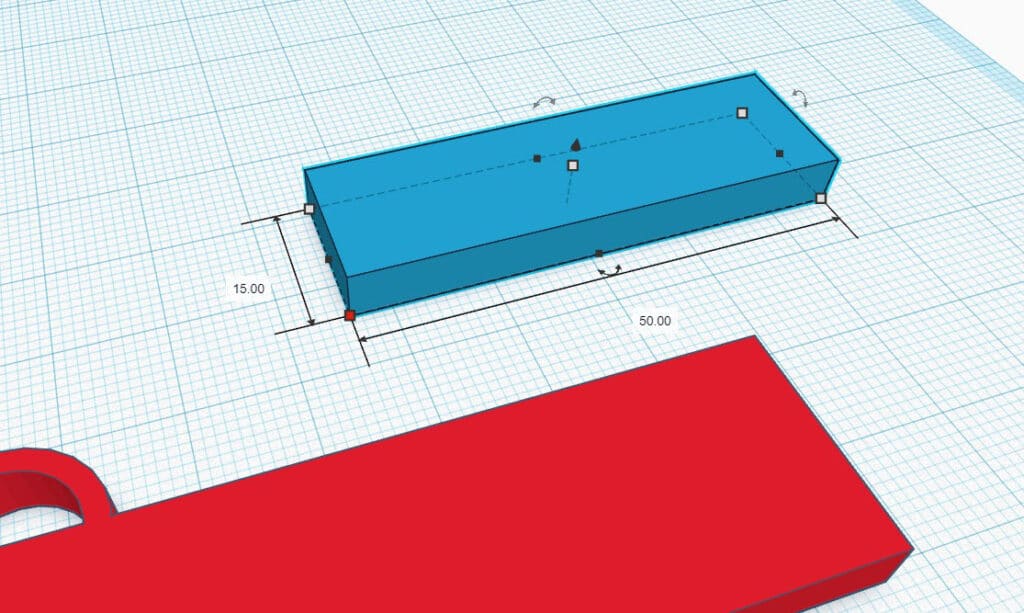
6. Make this box the same height as the other box, but also slightly smaller than the other box in the other axes. I used 15mm tall by 55mm by 5mm.
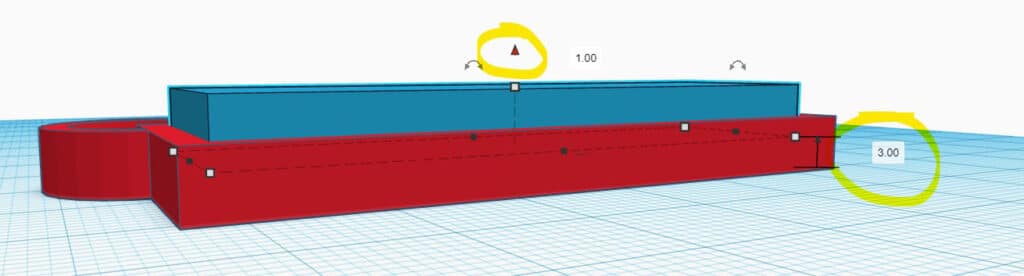
7. Place the new box in the first box somewhat near the center. You can use the arrows keys on your keyboard to more accurately place models. Then, using the black arrow that is visible when you select the box, raise the new box by 2 or 3 mm.
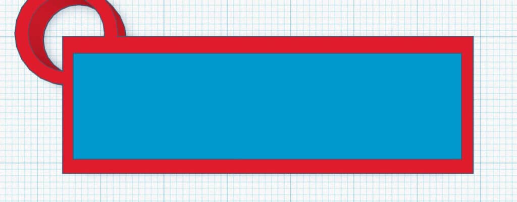
8. With the new box still selected, select hole in the shape menu on the right side. Select both models and click the group in the upper right hand corner to subtract the new box and make a cavity.
9. Next, select the work plane option in the upper right corner. Click on the big surface of the cavity/impression that was just made. This will create a new work plane that your models will start on when bringing them in.
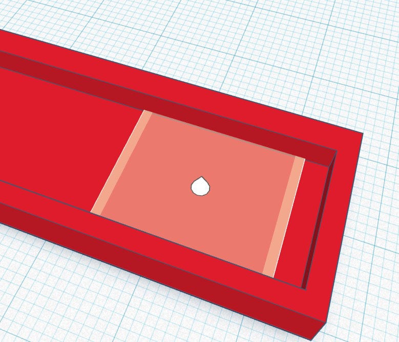
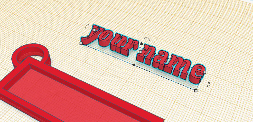
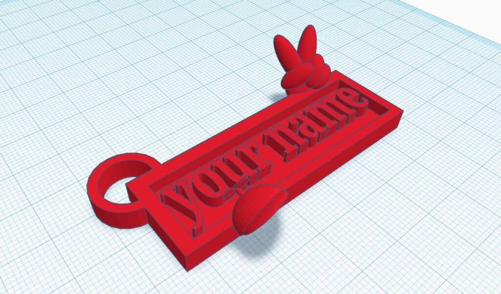
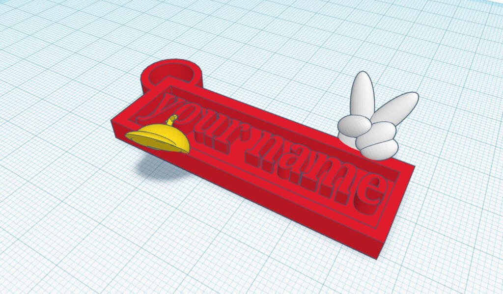
10. Next, in the Model Menu, use the drop down menu to select text and numbers located under basic shapes. Click text and drag into the work space.
11. Click text and in the shape menu and type your desired text (in this case, a name) where it says” text.” You can also edit the font underneath where you change the text.
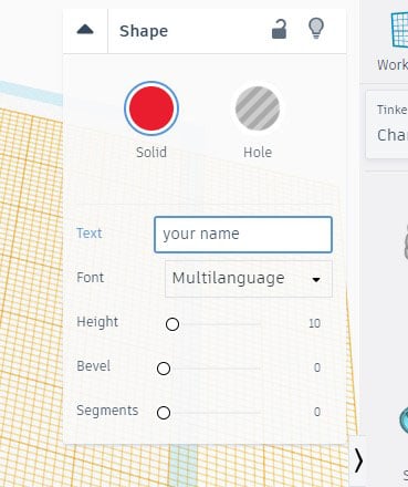
12. Next, we will resize the text like we did with the shapes. Adjust the size using the black or grey boxes that appear when you select the model. I made mine just slightly smaller than the cavity at 3 mm tall.
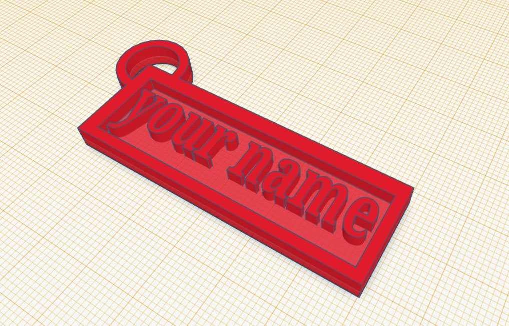
13. Select all the shapes again by clicking and dragging or shift clicking. Group them to combine them. Remove the yellow workplane by selecting the work plane on the right side and clicking anywhere on the plane.
14. Your name tag is now complete! Feel free to browse TinkerCAD’s pre-existing model using the Model Menu on the right side and customize it to your liking!
Email your designs to project@the3dprintingstore.com for the perfect print with a 10% discount if you mention this article. Make sure to tag us on social media and we’ll repost what you create!
This series explores each of the numerous slicer settings available in most 3D slicing softwares. Last time we looked at the settings for controlling your extruder. This time we will look at how to control the layer settings for your prints.
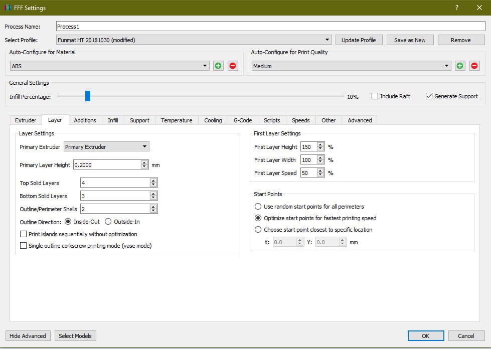
Primary Extruder
This option allows you to pick an extruder from the dropdown and set the layer settings for each extruder individually. Most users only have single extruder printers, so this option is not pertinent. However, if your printer is a dual or triple extruder printer this can be an important setting to achieve customized print settings for the different materials or colors you are working with.
Primary Layer Height
The layer height has a direct relationship to print time and resolution of the print. This setting is one that you will change frequently depending on the circumstances for your print. If the part does not need to be very high resolution, it is always best to put a larger layer height as this will print faster. Layer height and print time pretty much scale linearly, so if a 0.3mm layer height print takes 5 hours, that same print at 0.2mm will take 7.5 hours. However, if you need a higher resolution print and are not concerned about the time, then high resolutions can save post processing time. For most consumer printers the nozzle size is 0.4mm and the upper bound of layer height you should use for a nozzle is 80% the diameter of the nozzle; otherwise, you can build up pressure in the nozzle. So, for most printers the upper range is 0.32mm. There isn’t technically a lower limit based on the nozzle size as this is more determined by the stepper motors on your printer and their resolution. A healthy lower limit would be 0.5mm, but even still most people do not go below 0.1mm.
Top Solid Layers
The amount of top solid layers can have a large impact on surface quality for the print. This setting tells the printer where to stop printing infill and start printing solid layers again close off the print. A pretty common value is 4 layers. This means at any top surface point there are four completely solid layers below that point. This can help improve strength and also improve quality. If you are printing a part with low infill, you will probably need to increase the amount of top layers to save material and print time. The reason for this is because the spacing between infill is now larger and will require further bridging over the space between the infill. This can lead to sagging. The more top layers you have, the more likely this is to be corrected as you start building a solid foundation underneath the current top layer with the previous top layer. If you are printing with low infill and are seeing small voids in the top, this may be an easy solution. The more top layers you add though, the longer the print time will be because you are replacing infill layers with solid layers which take significantly longer to print.
Bottom Solid Layers
Bottom solid layers are similar to the foundation of a house. They build a strong solid surface for the rest of the print to build upon. This number tells the printer at what point to stop printing solid layers and start printing infill. A typical value is 3 layers. You may notice that this is lower than the top solid layers. This is because the material is being printed on a nice flat bed, so there is no concern for dropping or voiding like the top layers might see.
Outline Perimeter Shells
As we have covered the top and bottom of the print, this setting controls the side or walls of the print. It basically determines how thick the part is everywhere besides the top and the bottom. A good value here is 2 walls for a 0.4mm nozzle. This provides great strength while still keeping print time to a minimum. If you are using a different size nozzle, you may be able to get away with less or more walls as the lines become thicker or thinner.
Outline Direction
This option selects whether the wall layers start from the inside wall and work out or whether they start on the outside visible layer and work their way in as the print goes. Most of the time it is best to leave this setting as inside-out. This allows for any small print problems that may occur from retraction or something else to be fixed on the inside layers that are not visible to people while keeping the outside layers nice and clean. Also, inside-out is good for parts with steep overhangs as it gives more surface for the material to grab on overhangs.
Print Islands Sequentially Without Optimization
“Islands” in 3D printing describe parts of a print not connected to anything else in the x-y plane for a given layer. Basically, this means that if the extruder has to travel from one spot to another without laying material on a given layer that it is travelling between two different islands. If the print islands sequentially without optimization setting turned off, the printer will optimize the print for time and speed by reducing the number of travels between parts. This usually leads to the printer printing a layer and then immediately printing another layer on top of that for the same island. Then, it travels rather than traveling between the two islands every time, essentially reducing the travels to half. This works fine if the islands are large and gives the material enough time to cool down. However, if you are printing small islands, the printer can immediately start printing a layer on top of material that has not been given the opportunity to cool down completely. This can cause the material to burn, melt, result in blobs, scorch marks, etc. By selecting this option, you can force the printer to switch between islands giving each island proper time to cool down before printing the next layer on top of it.
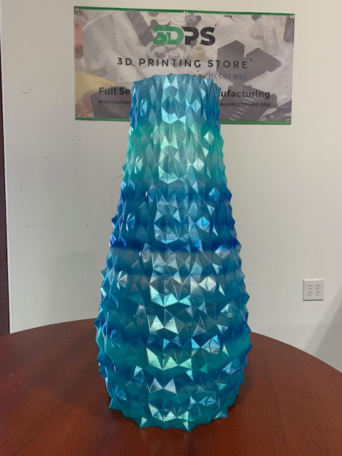
Single Outline Corkscrew Printing Mode (Vase Mode)
This option is for parts that only need a single continuous wall. Essentially, the extruder extrudes throughout the entire print slowly– building on top of previous layers without ever needing to retract or travel. This saves considerable amounts of time. However, it is only usable in very specific settings. If your part has any islands or requires more than a single wall for strength, this setting cannot be used successfully. As the name implies, it is very useful for vases or any single body container.
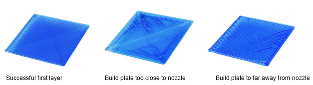
First Layer Height
The first layer is often the most crucial setting for any print. Most of the time, if the first layer comes out correctly, then the rest of the print will be successful as well. In order to try and ensure proper adhesion, it is possible to change the settings for the first layer. One of these settings is the first layer height. The first layer height will increase or decrease the vertical thickness of the first layer by the specified percentage. We recommend using a slight increase such as 120% to help improve any slight defects in the build plate such as scratches or chips. It also creates more surface area to improve adhesion.
First Layer Width
The first layer width adjusts how thick the first layer is going to be. This can help with first layer adhesion to the bed. When it is increased, it increases the surface area. Using small nozzles can benefit from this setting being increased. However, increasing this too much can create an “elephant’s foot” on the print. An elephant’s foot is when there is excess material on the first layers from material being over-extruded.
First Layer Speed
This dictates how quickly the extruder moves during the first layer of printing. Reducing the print speed for the first layer can reduce the chance of any imperfections during printing of the first layer. This will provide better adhesion and a solid base layer for the rest of your print to be built upon. We recommend running this somewhere between 70% to 100%.
Start Points
There are three options for this setting. Each can be useful depending on your project requirements.
“Use random start points for all perimeters” does exactly what it says. For every perimeter, or wall, the slicer selects a random point on the perimeter to start extruding. A little excess material can create a small blob at the beginning of a perimeter; under-extrusion can occur leaving a small void and this leaves small noticeable imperfections on the print. If the starting points are randomized, these slight imperfections can be less noticeable.
“Optimize start points for fastest printing speed” allows for faster print times by reducing the amount of travels or the travel distance. This can also create problems though by creating a seam that runs vertically along the part; often the fastest place to start a new layer is where the previous layer ended. This can apply extra heat and/or material to the previous layers endpoint which creates burns or blobs; when this is done over the entire print for every layer or most layers, it can create a vertical line that is visually different along the part.
“Choose start point closest to specific location” allows you to input an x and y coordinate; then, every layer will be analyzed where the closest point on the part is relative to the coordinate pair. This can be useful if you have a face or surface that will be hidden or is less visible. If so, you can orient the part to face a given coordinate and set the start point at that coordinate. This will hide any imperfections from start points in a less visible area.
If you want to get your printer working optimally, contact us at project@the3dprintingstore.com or call at +1 720-443-3733
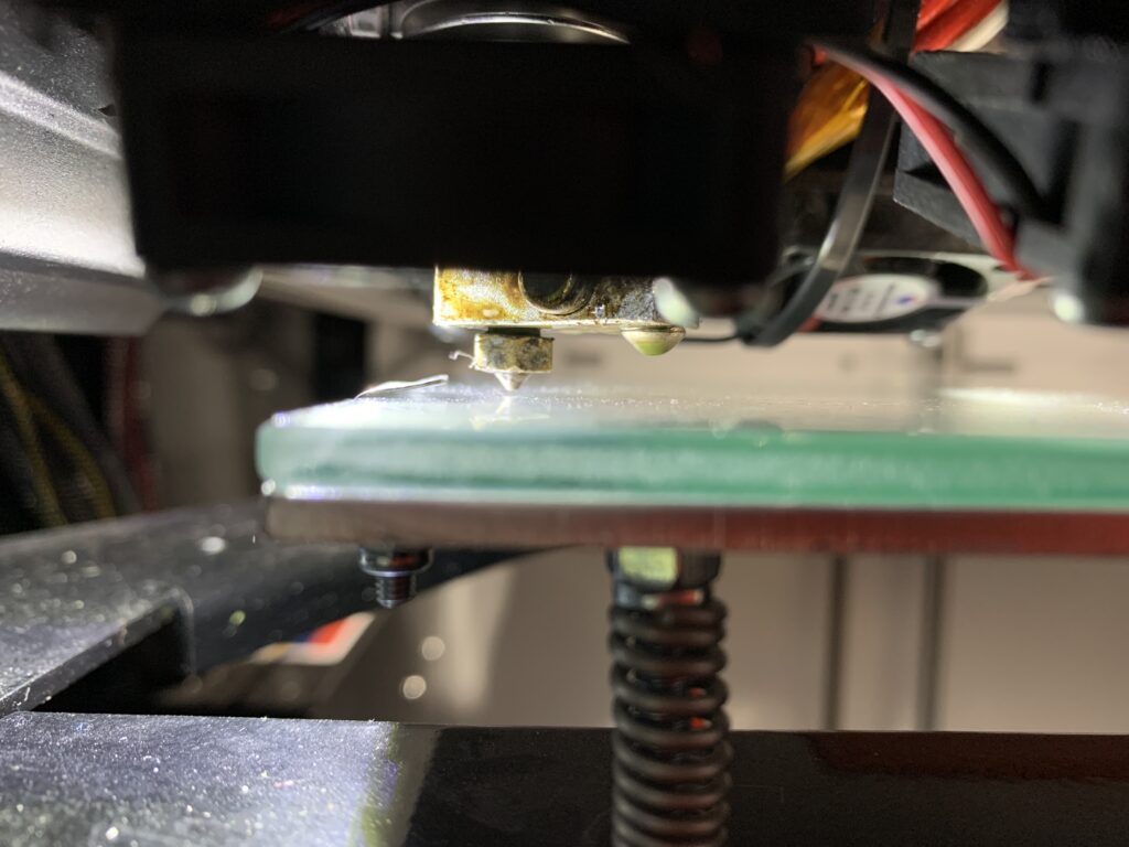
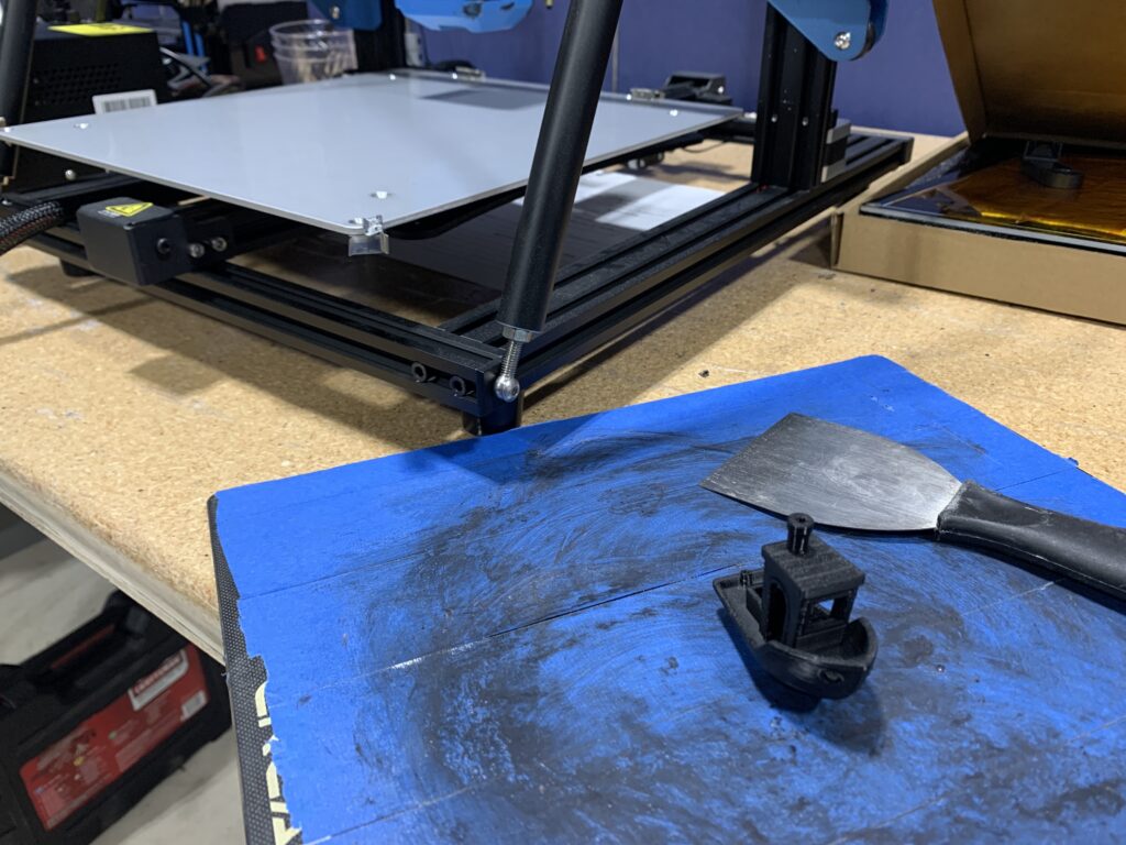
Tempered Glass
One of the best and easiest upgrades you can perform to an Ender 3 printer is a tempered glass bed. Creality offers a bed that is perforated and composed of carbon silica. This bed offers a few advantages over the flexible bed that typically comes stock with an Ender 3.
Prints stick better to this bed. Unlike the flexible bed, the glass build plate is already perforated which improves first layer adhesion as there are small holes for the filament to get into. The glass also has the availability of adding other compounds to improve adhesion such as a glue stick, hairspray, etc. Applying these products to the flexible bed would work. However, removing the adhesive products from the flexible build plate can be troublesome.
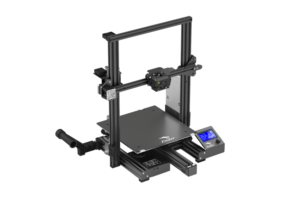
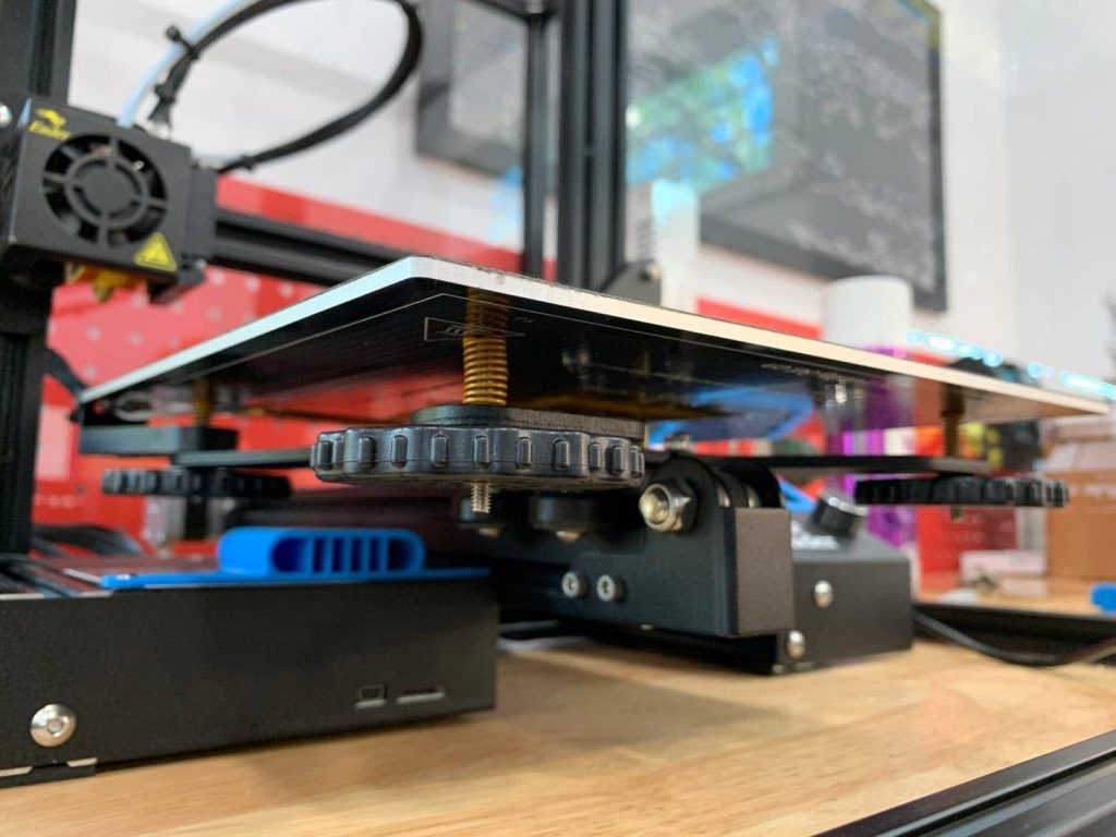
Bed Leveling Wheels and Springs
Out of the box, Ender 3s (like most other printers) will have 4 springs and 4 knobs underneath the print bed. These are used for leveling the bed. These knobs are notoriously small and can make it difficult to level the bed. In addition, the springs lose compression over time.
An upgrade can replace the stock bedknobs with larger diameter wheels and thicker springs. This upgrade helps a few things. Firstly, it helps with the general level process– not as much of the wheel needs to be turned to make small adjustments. This means that the speed of which you level the bed as well as accuracy is increased. These knobs are also much easier to locate and control when turning– which again helps with time and accuracy of leveling the bed.
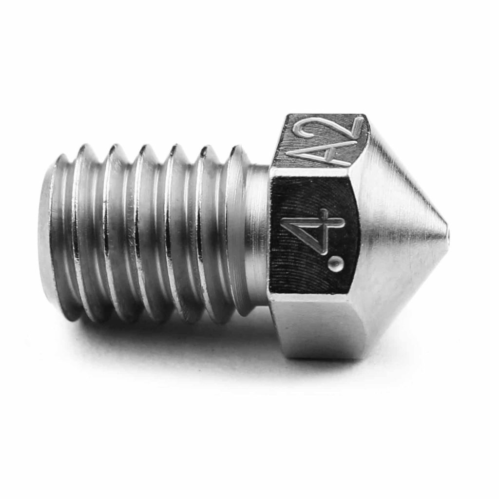
Nozzle
Ender 3s, as well as numerous other printers, typically come installed with a .4mm brass nozzle. These nozzles work great– especially if you are using PLA exclusively as your filament. However, over time, these nozzles can start to break down due to heat and friction.
There are many third party companies such as Microswiss that produce nozzles that are made from harder materials like hardened steel and even ruby! These nozzles excel in a couple things. They generally last longer since they are made of a harder material. They are also optimal for printing higher end materials such as carbon fiber. Generally, brass nozzles are not suited for high abrasive filaments.
Nozzles also come in a variety of sizes ranging from .2mm up to 1.5mm.
With a larger nozzle diameter, you can print faster. However, quality is then sacrificed.
Layer height is typically defined by nozzle size. The general rule of thumb is that the layer height should not be much more than half of the nozzle diameter. So, if you are using a .4mm nozzle, then it is generally ideal to use a .2mm layer height.
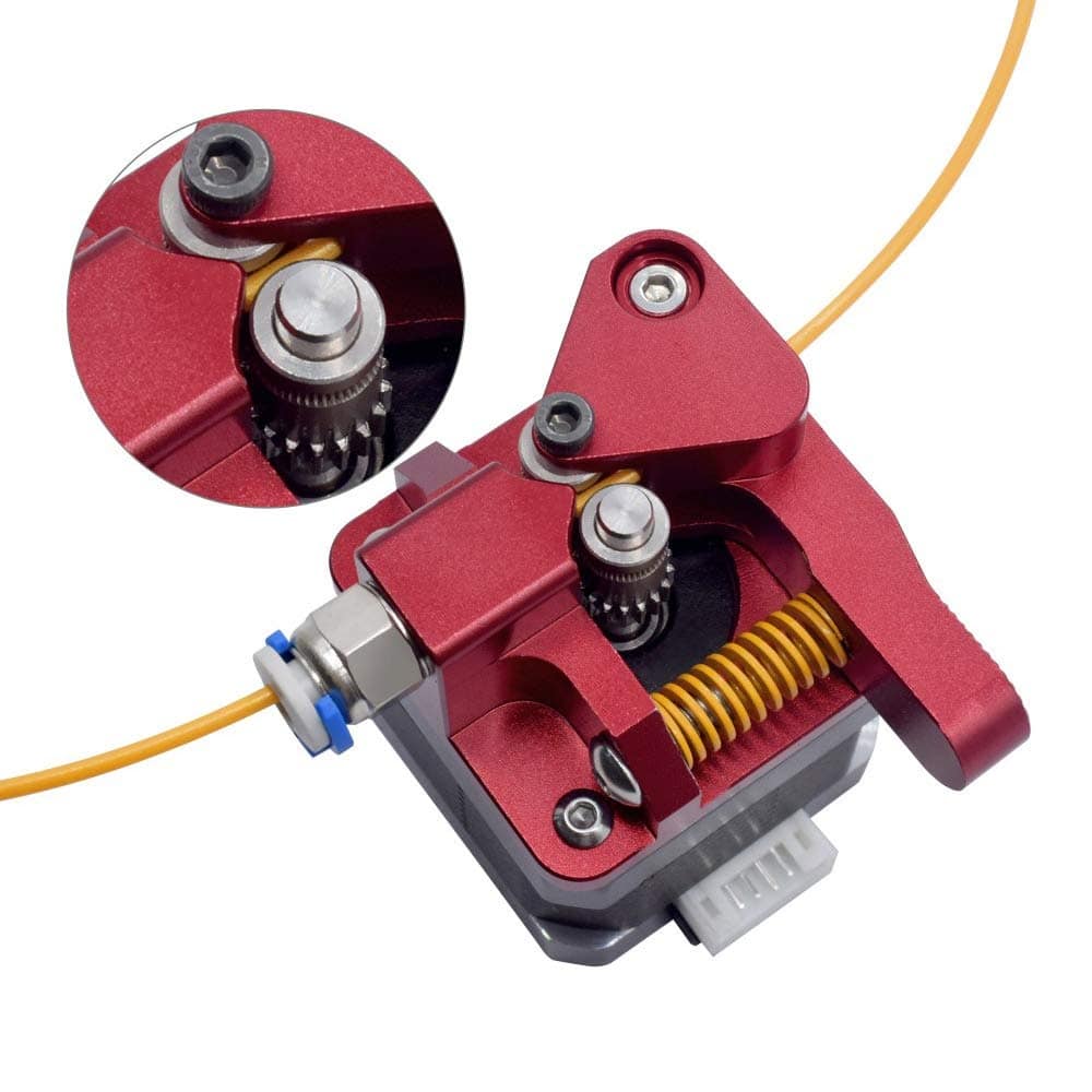
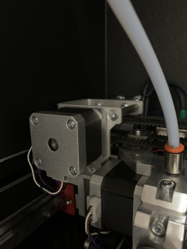
Extruder
Ender 3s as well as other Creality printers typically come with an extruder that is loathed on the left side of your printer. This part is made with plastic, and after time the plastic can become brittle and break. This will cause the drive gear within the extruder to lose grip on the filament. Then, the filament will no longer extrude properly or at all.
There are third party companies that make an upgraded extruder that is compatible with stock Creality machines. This upgrade offers a few improvements over its predecessor. The body is made from metal components; so, the chances of it breaking are much less. New systems also offer a dual feed system. This basically means that there are two drive gears pushing the filament rather than the conventional one. This helps keep a constant flow rate of filament from the nozzle. The spring is also upgraded so that it keeps proper tension on your filament over time without adjusting it.
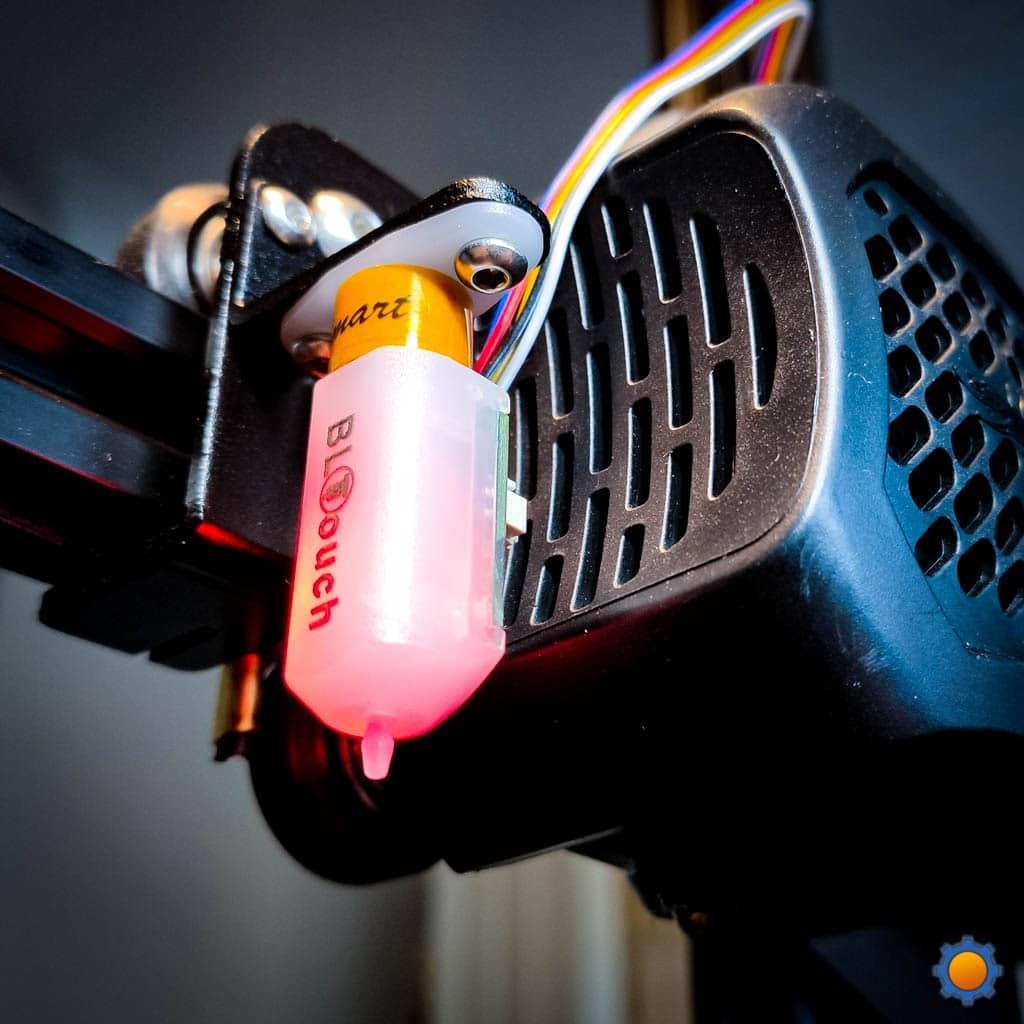
BL Touch
The current method for leveling a bed is to use a sheet of paper and place it under your nozzle and while turning the knobs until there is very little friction. However, this method has its own flaws. Beds can become unlevel very easily if you are not careful. Additionally, if you apply a lot of force to the bed when removing a part, this can unlevel it as well. Manually leveling your printer is now a thing of the past.
Creality has teamed up with ANTCLABS to develop the BL Touch which is an auto leveling system for your printer. This system is easy to install and can save you a lot of time on future leveling. This system uses a probe to tell the printer the bed height at multiple locations. The printer is then able to adapt to those heights to raise and lower itself accordingly. The system is not totally foolproof. However, it holds promise if you are having to level your bed before every print.
As always, The 3D Printing Store team is available to provide demonstrations, professional development courses, and educational courses to you and your team. Contact us or email arausch@the3dprintingstore.com for inquiries.
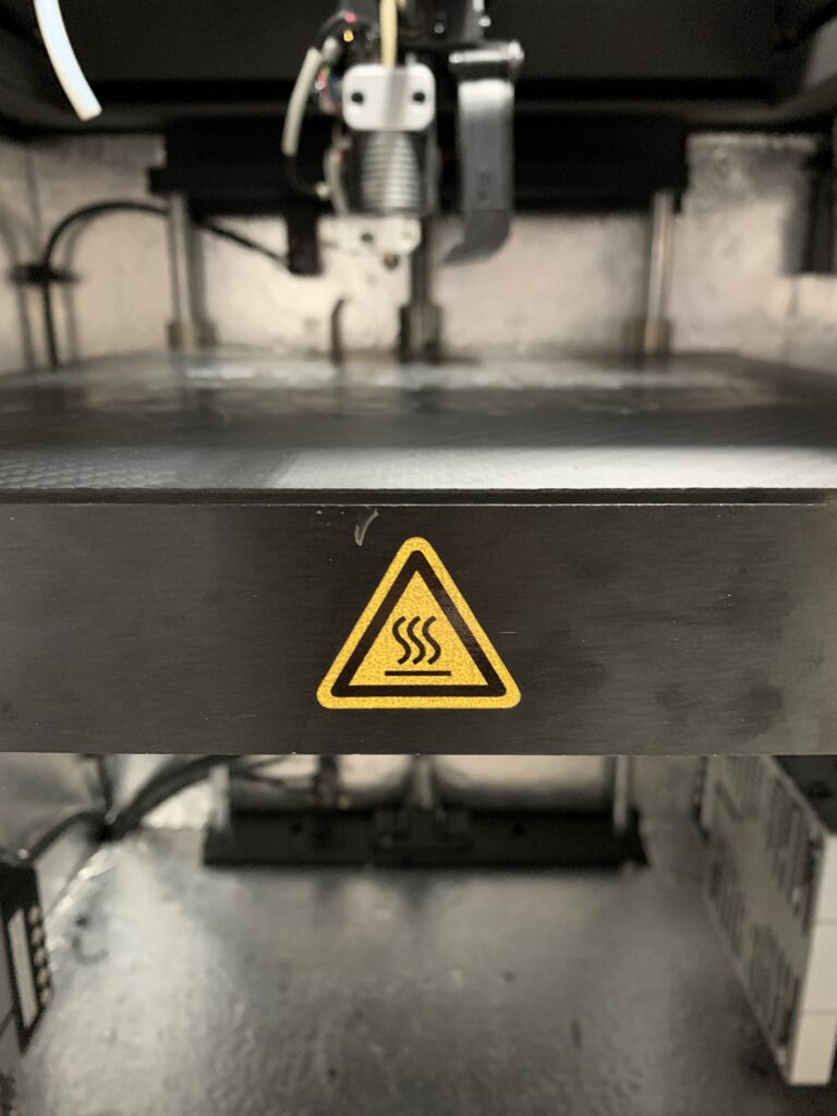
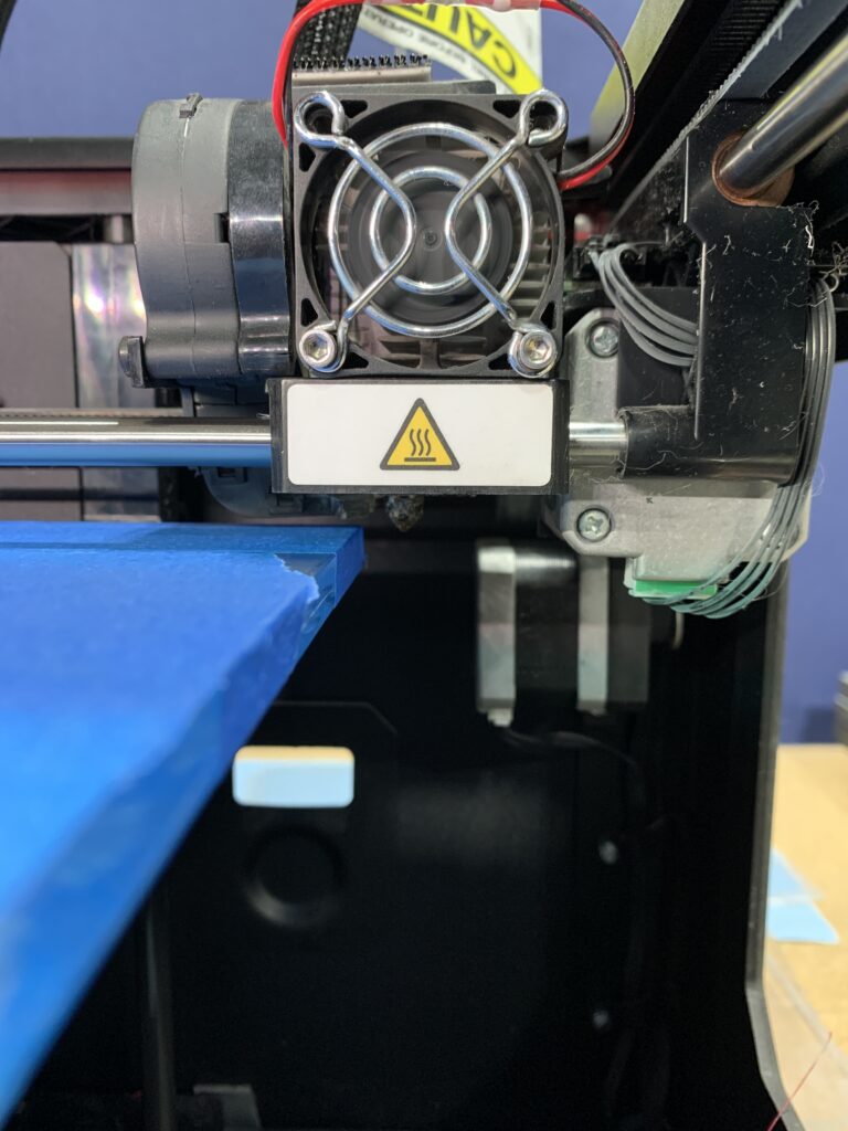
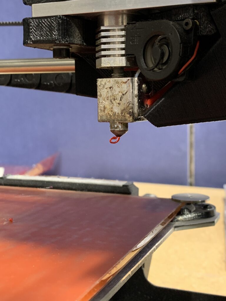
Hot ends
Hot ends are one of the most dangerous parts of a 3d printer as they can achieve extremely high temperatures– up to 320c in some cases. A user can forget the hot end is on as there is typically no way of determining how hot a nozzle is unless you look at the interface, which not all printers have. It is extremely important to keep your hands away from this during printing and even after printing for about 5 minutes to allow the nozzle to cool.
The same goes for hot beds as these can achieve high temperatures as well.
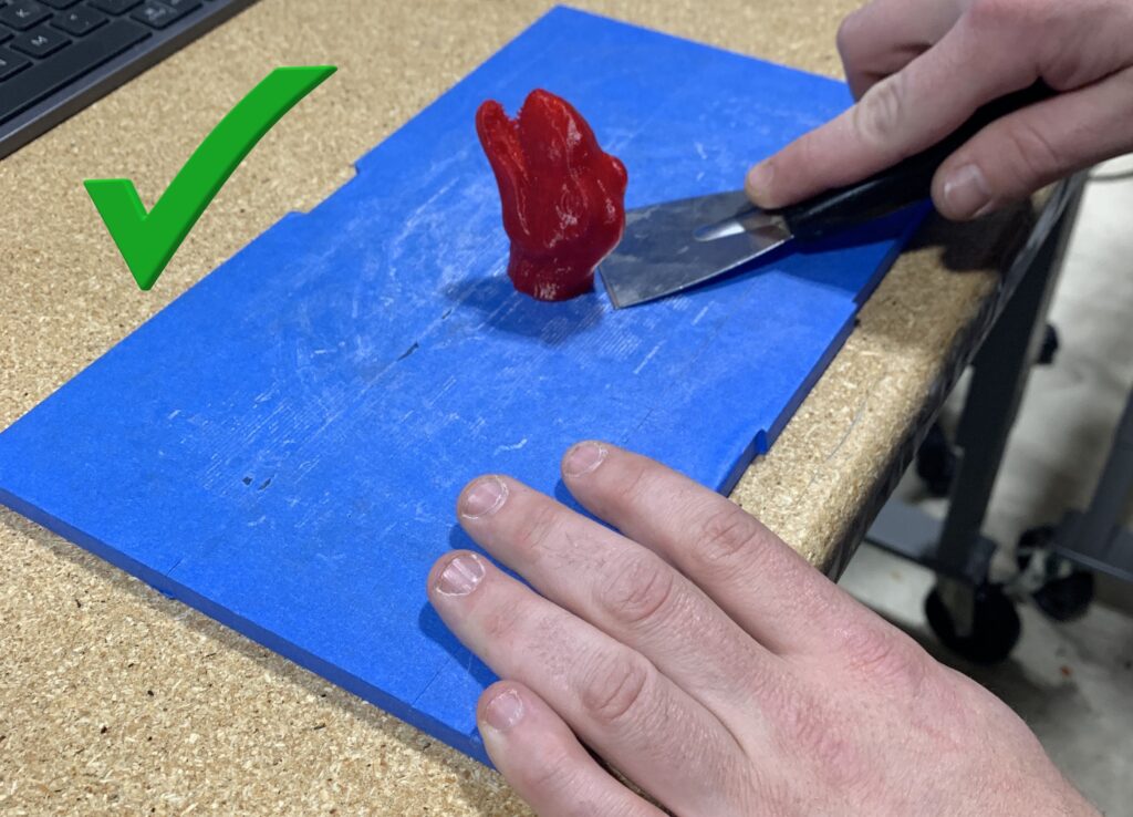
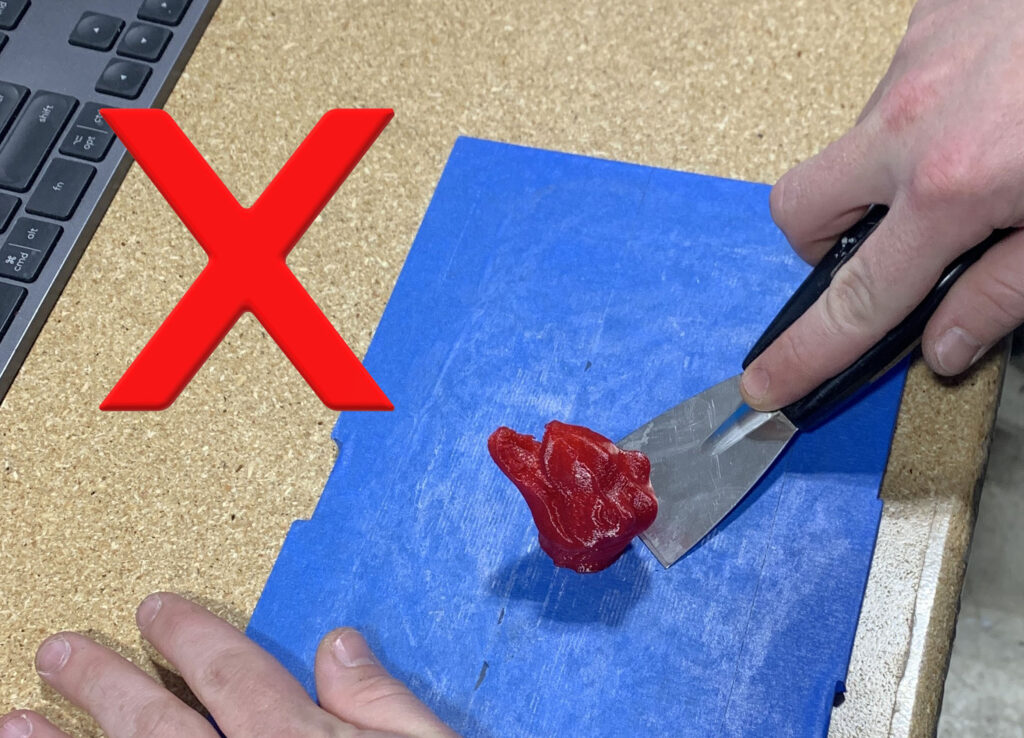
Part removal
When removing parts from your build plate, it is important to keep your hand clear of the path in which your spatula/removal tool is moving. These tools tend to be very sharp, and it is very easy to cut oneself if not careful. This is especially important if you are using or removing your bed to remove the print. Some prints may stick to beds better than others and require more force to remove. This is typically when an incident occurs as the part requires a lot of force initially to remove the part but once the part has started separating, there’s very little to stop the spatula/removal tool from continuing.
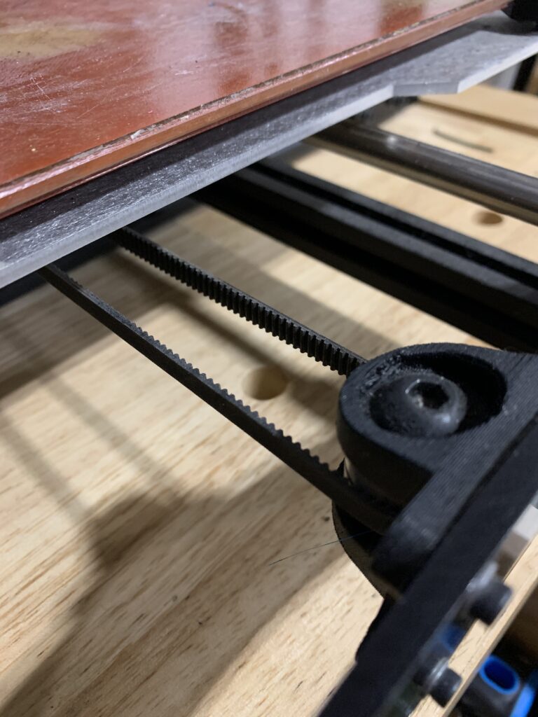
Motors
Printers use stepper motors to move the extruder and bed to different locations. Commercial printers typically use a NEMA-17 stepper motor and these do not produce enough power to cause serious injury. However, it is still important to keep fingers clear of moving components during printing as there may be a moving component such as gear that you cannot see as well as to avoid electrical shock. It is also important to keep facial hair away from any moving components such as belts and pulleys, for example.
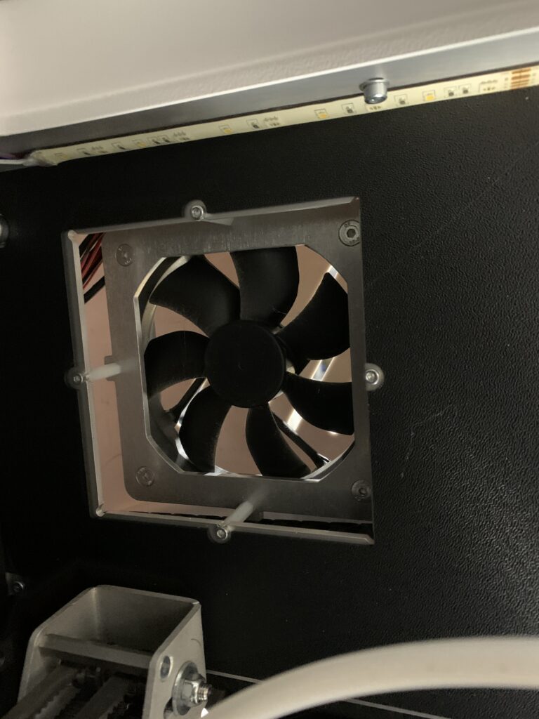
Materials
Some materials can be dangerous to print. Even though you cannot see it, printers release gases as well as small particulates into the air when printing. Some materials are safer than others such as PLA– this is regarded as a safe material for hobbyists. ABS, however, can be harmful as it releases carcinogens into the air. Make sure to check your filaments recommended safety instructions before printing. Also, make sure to use proper ventilation where you are printing.
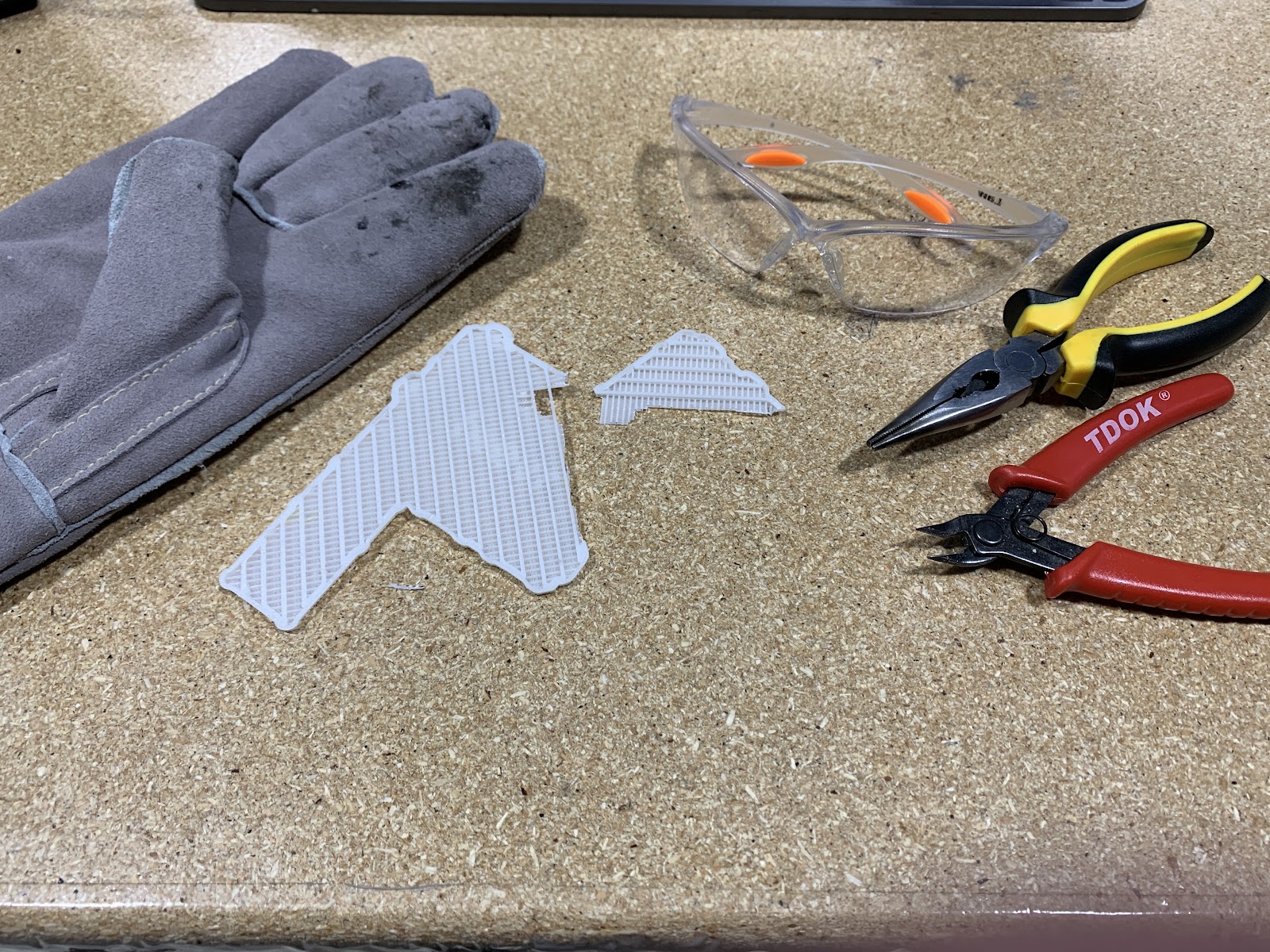
Support removal
It is important to be very careful if removing supports from you part. Depending on materials, supports can break and become extremely sharp. It is recommended to wear protective equipment such as leather gloves and eye protection when removing support to reduce the risk of injury.
As always, The 3D Printing Store team is available to provide demonstrations, professional development courses, and educational courses to you and your team. Contact us or email arausch@the3dprintingstore.com for inquiries.
5 Tips for Post-Processing Your Parts
Filling Gaps
Parts may experience under extrusion in some areas, or just in general, that need to have added material. This can be done easily using some of the following products.
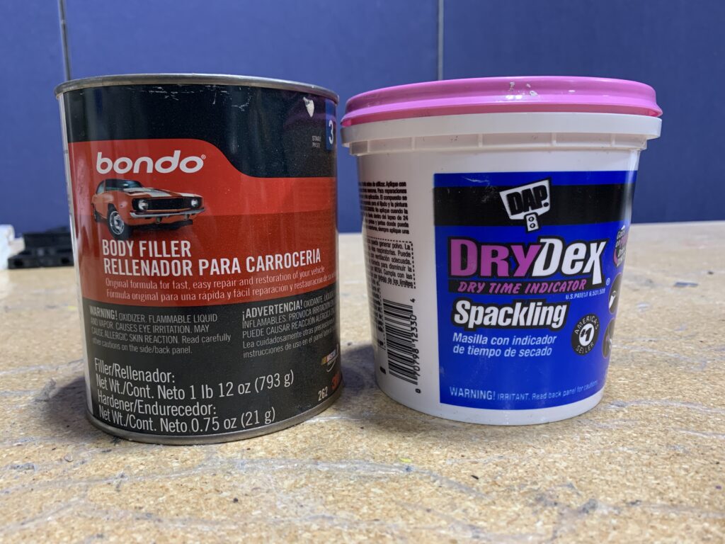
Bondo
Bondo works well for filling large gaps and dries to a very hard surface. Make sure to use proper ventilation and read the manufacturing directions before use.
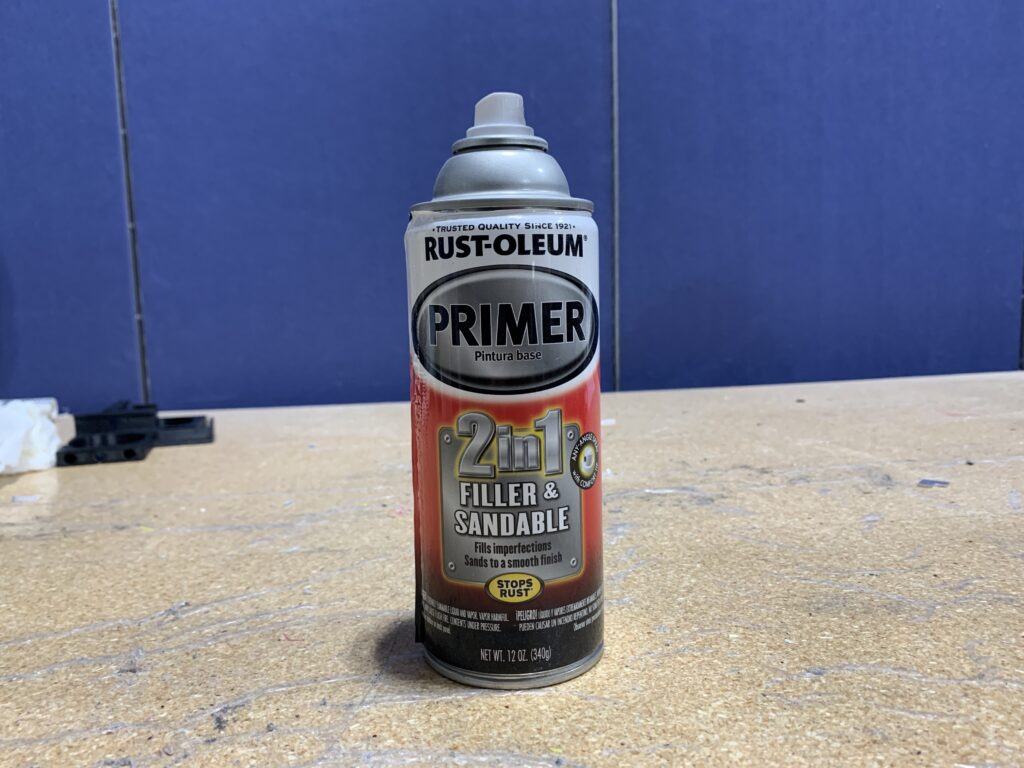
Filling Primer
Primer can come in different densities and forms. Filler primer is commonly found at automotive stores. It can be used to fill small gaps and can be sanded smooth for painting. It also dries very fast.
Drywall Compound
This is the most cost efficient option and can be used to fill large or small gaps. The larger the gap, the longer it will take to dry. It shouldn’t be used on a surface that will receive force as the compound can be soft even after drying.
Sanding
Sanding Block
Whenever sanding a flat surface, or even a convex surface, it is recommended to use a sanding block or hard flat surface. This will help the surface stay flat and either parallel or perpendicular to adjacent surfaces. It will also help prevent divots that can be caused by sanding with an apparatus such as your hands.
Files
Files work great for raw prints as they can remove material rather quickly. They also come in various sizes and shapes that can help you maintain the intended form.
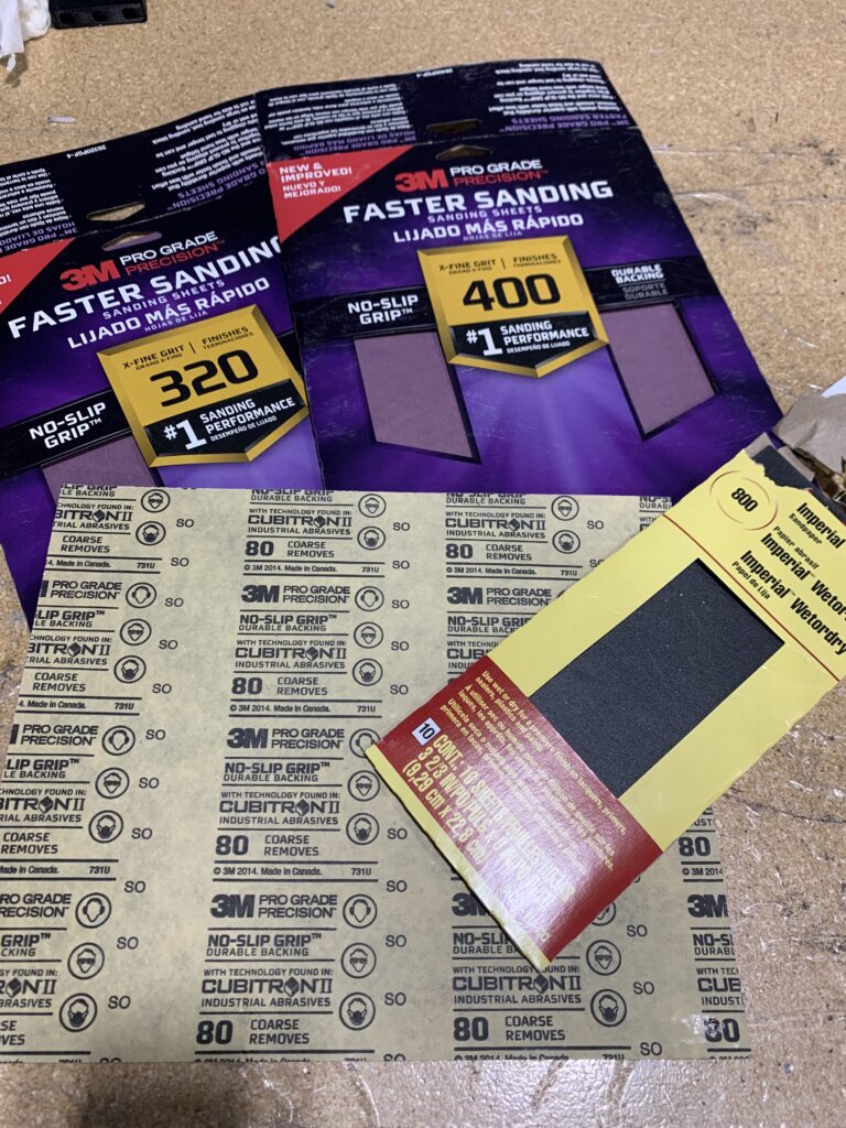
Grit
Sandpaper grits make a big difference and can range anywhere from 60 grit up to 2000 grit, and further. For general sanding for paint, you shouldn’t need more than 400 grit.
The lower the grit, the rougher the sandpaper. Grits in the range from 60-220 should be used on raw prints/plastic. After priming the part, grits that range from 220-400 should be used to get a smooth surface for paint. Anything above these grits is generally used for polishing purposes.
Priming
Coats
The number and the thickness of coats matters! It is recommended to do more light coats than less, heavier coats. Heavier coats will take gradually longer to properly dry. If the primer does not properly dry, it can cause issues with sanding. Make sure to use primer in a well-ventilated area and read the manufacturer’s intended directions.
Quality
Quality of primer makes a difference. There are brands such as Duplicolor™ that are automotive primers. It is good for hard surfaces. This typically dries faster than other primers as well, such as the Rustoleum ™ primer. This type of primer is recommended for surfaces that require more flex.
Painting
Cleaning
It is very important to make sure you properly clean your part from any dust or debris before painting. Using products such as cheese cloth or mineral spirits helps in this process.
Coats
Much like primer, it is recommended to use lighter coats. This will help the paint dry faster and bond better to the surface. Make sure to paint in a well-ventilated area.
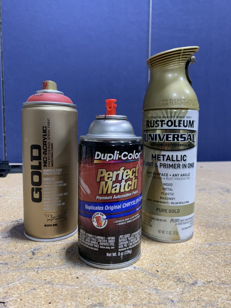
Quality/Brand
The quality of spray paints makes a huge difference when painting your part. You get what you pay for typically in this instance. Paint also comes in a variety of styles such as glossy, satin, or matte. Duplicolor™ typically is a good paint for hard surfaces as it is an automotive paint. A downside to this brand is color selection. Rustoleum™ paints typically take longer to dry, but are usually more effective on a surface that requires more flexibility.
Polishing
Clear Coat
After painting, it is recommended to apply a clear coat over the paint. This will help protect the paint from impacts. Like paint, this also comes in a variety of styles such as glossy, satin, or matte. Apply in a well-ventilated area and check the manufacturer’s directions that should be located on the can.
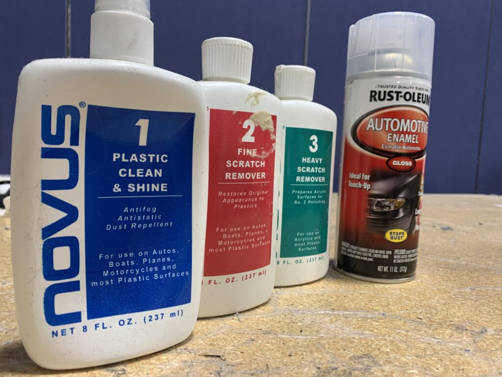
Shine!
After the clear coat has properly cured for the manufacturer’s recommended time, you can polish the clear coat to the desired finish. If you are looking for a high shine finish, it is recommended to use a glossy clear coat. Wet sand this clear coat using a sandpaper grit of 600 or more. Eventually move from sand paper to a polish compound such as Novus ™ product and use their hierarchy of polishes.
As always, The 3D Printing Store team is available to provide demonstrations, professional development courses, and educational courses to you and your team. Contact us or email arausch@the3dprintingstore.com for inquiries.
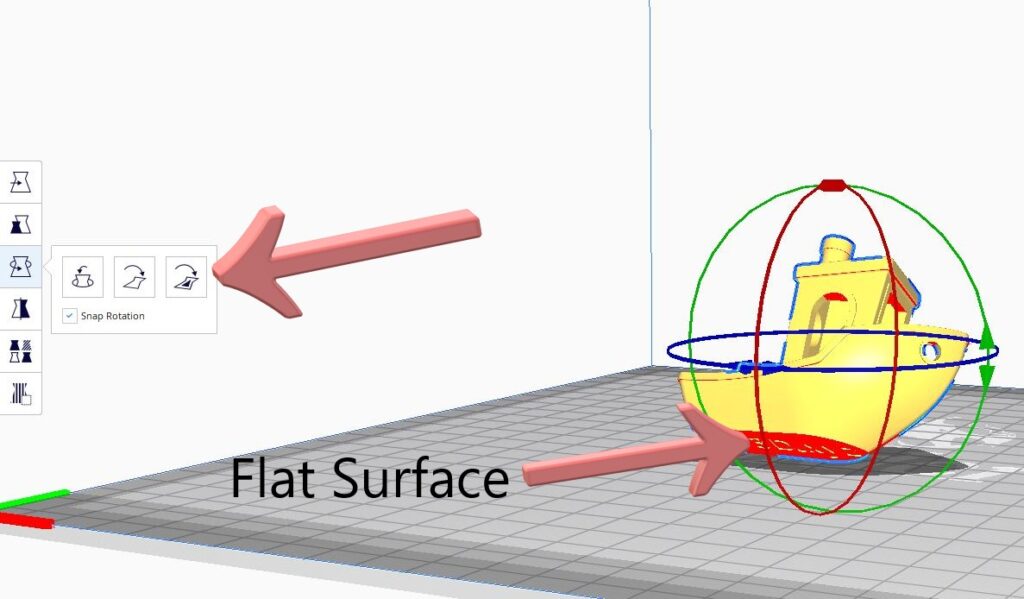
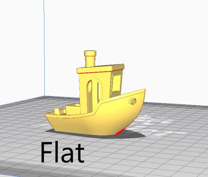
Build Plate Orientation
You can select a flat face on your model and Cura will put this face on the print bed. This saves time guessing and checking if your print is fully seated on the build plate.
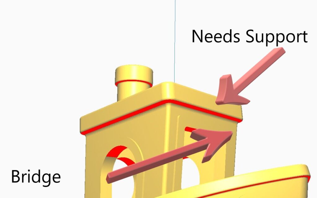
Supporting
Models that have areas highlighted in red generally require support material. Some areas may be able to be “bridged” if they are connected at both ends and the distance is not too great. It is recommended to use the bridging calibration print that is found on Thingiverse to find out how far your printer can go!
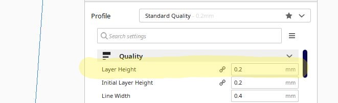
Layer Height
Layer height is typically depicted by nozzle size. General rule of thumb is the layer height should not be much more than half the nozzle diameter. So, if you are using a .4mm nozzle, then it is generally ideal to use a .2 layer height. The larger the layer height, the less time the print will take; however, this value can negatively impact final quality.
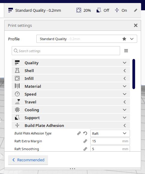
Buildplate Adhesion
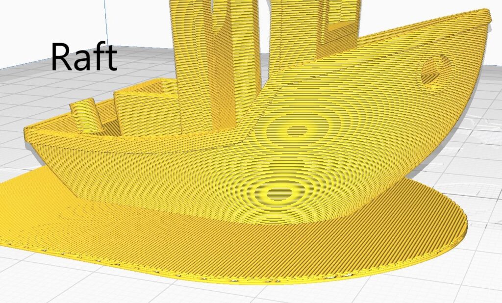
If you’re having trouble getting your part to stick, or it is tall and narrow and prone to falling over, Cura has a few options that can help with the parts adhesion to the bed. There is the “raft” option which builds layers of filament under your print. This raft typically adheres better to the bed due to larger surface area as well as speed variables.
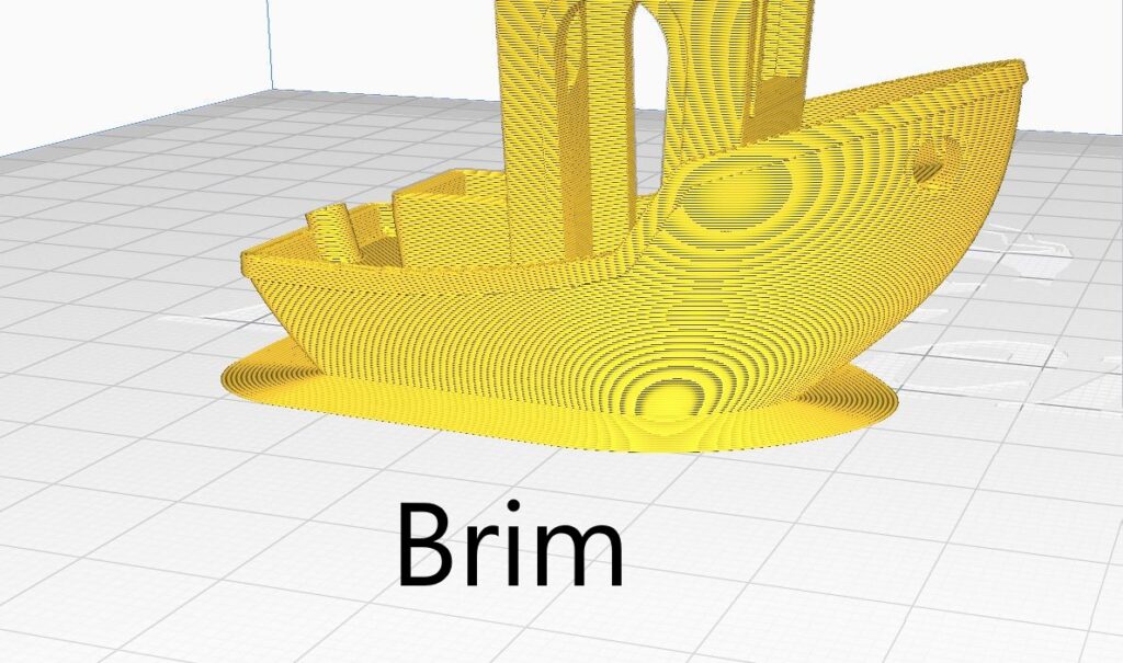
The other option is to use a “brim.” This builds layers on the exterior of the part increasing it the parts surface area. A brim differs from a raft as a raft will leave the part off the build plate slightly and a brim leaves the part on the build plate.
These settings can be found in the “Build Plate Adhesion” tab in “Print Settings”
Material Usage
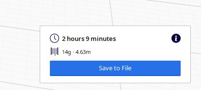
After slicing the file, Cura will have a prompt in the bottom left corner of the screen. Here it displays information on how long the print will take as well as how much material it is estimating it will use. This is helpful with larger prints so you can check if you have enough material before starting the print.
As always, The 3D Printing Store team is available to provide demonstrations, professional development courses, and educational courses to you and your team. Contact us or email info@the3dprintingstore.com for inquiries.
In Part 1 of this exploration, we examined how designing useful, functional parts is a significant barrier in the widespread adoption of 3D printing. We looked at what strides have been made already to address this issue and what the future might hold. In Part 2, we will examine how print preparation has contributed to massive frustration with printing– what has been and what might be done to improve this experience.
The Problem
How many settings do you think there are for a 3D printer? If we stop to consider a 3D printer, there are really only 4 or 5 moving parts, a stepper motor for each of the x, y, and z axes, one for the extruder, and maybe a fan or two. In addition, you have a heater for the extruder and maybe one for the bed. If we assume that each of those pieces has about 8-10 different variables that you can change, that’s ~60 different settings. That sure seems like a lot. But if you look at any of the commonly used slicers today, you’ll realize that most slicing programs have significantly more than that. As of right now, there are over 140 different settings that can be adjusted in Simplify3D, a popular slicing program. With each of the settings comes many values that can be set– leading to millions of different combinations for a complete print profile. Choosing the right one for your print to come out how you envision is not simple. You can try to brute force every combination, but that is not a good strategy with a 3 or 4 digit combination lock– let alone a 140 digit one.
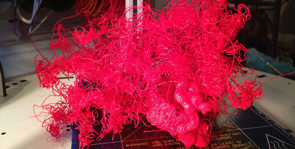
How best can you solve this seemingly massive undertaking? Are 3D printing experts Gods amongst Men? As much as many of us in the industry would like to think so, we surely are not. The truth is that many of those 140 variables do not need to be changed in order to have some level of success. There are multiple combinations that work for the lock, even if some of them result in less desirable prints. But how does someone know which variables are the most important? And what values to set those at? And, how does one know if changing any of those variables has an effect on other variables? And so on. This is one problem inherent with the widespread adoption of 3D printing. It is definitely not as simple as it was hyped up to be. With an inkjet 2D printer, people install the ink cartridge, hook it up to their computer, and hit print. The average person wants a 3D printer to operate like their inkjet printer– not a machine that requires hours of research, trial and error, and luck– just to complete a simple print and not vomit a spaghetti pile of plastic on the floor.
Assuming that you are able to determine the correct variables to avoid a failure, the next step is to determine the right orientation and support for the part. This may sound trivial, but let’s look at even the most basic example– a cube. Common sense says to put it flat on the bed of the printer. For fused deposition modelling (FDM) printing with PLA material, this is the guaranteed best orientation; it requires no support and has a nice large surface for good adhesion to the build plate.
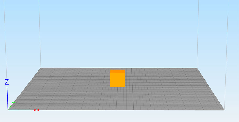
However, depending on your printer, if you wanted to print this in ABS maybe you would want to orient it differently to reduce the surface area contacting the build plate. ABS tends to warp on large surface area parts. If you printed this on an SLA or DLP printer, printing with the large surface area could create an elephant foot (an unwanted edge on the bottom of the part) or make the part very hard or impossible to get off the build plate without damaging the part, the build plate, or yourself. Also, if the cube is hollow and you print on a DLP printer, you could have problems with vacuum forces causing delamination. These are some of the factors to be considered when picking the optimal orientation for 3D printing and much more than someone would expect of a push and play system.
The next problem someone new to 3D printing encounters with print preparation is leveling the build plate and ensuring proper first layer adhesion. Proper first layer adhesion is probably the biggest factor in determining a successful print. Without a solid foundation, the whole house comes crumbling down. Leveling the build plate on the surface seems easy, but many people struggle to do it correctly and the failure to do so creates many problems later. A lot of systems currently give you nothing more than a sheet of paper, some hand screws, and a pat on the back. This is a skill that can be fine tuned, but all of the problems along the way such as damaged build plates, damaged nozzles, and clogged nozzles are off putting to someone who was promised immediate success with printing.
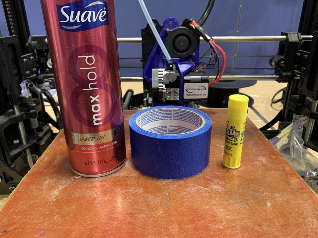
Even if you level the build plate correctly, you can still have poor adhesion. There are copious amounts of solutions for trying to improve adhesion: different build plate materials (such as glass, buildtak, painters tape, kapton tape, etc.) and adhesives ( such as glues sticks, glue sprays, hair spray, specially designed adhesives, and more). It can be overwhelming trying to find one that works for your printing needs.
Most people are busy and they don’t have the time or the mental energy to commit to learning all of these variables. Until 3D printing can truly become a push and play system with fewer than 10 choices, it will never have the level of widespread adoption that was depicted early on.
Where We Are Now
Many strides have been made to simplify the pre-print process and try to ensure success.
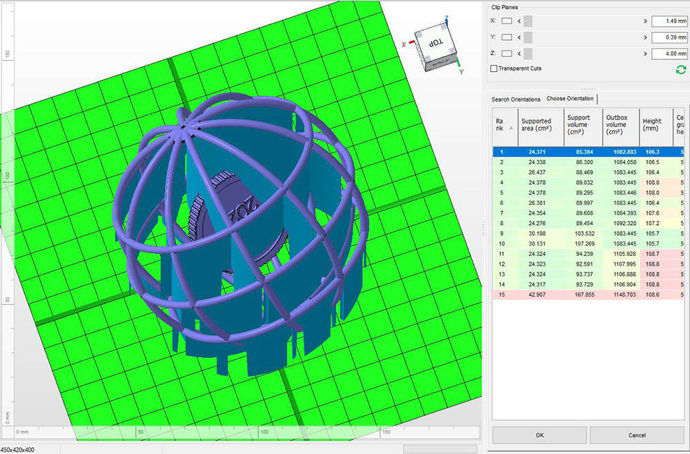
3D printer manufacturers, design software, and third party slicer programs have created software that attempt to offload some of the burden and make calls on many of the variables by running complex calculations based on a few key inputs. 3D software, like Netfabb, have an option to auto orient supports based on some key variables like minimizing support, maximizing surface area of the build plate, and more. The software essentially orients the part, calculates some of these key variables, and has a goal to find the minimum or maximum to optimize it. This is great and can be helpful on some complicated geometries, but it only can do this for a single variable. This means that it doesn’t always output the optimal orientation for the entire print, but only the optimal orientation for that specific variable.
3D printer and software companies have also tried to reduce the amount of adjustable variables for their machines by providing profiles for specific materials and limiting the options to resolution, support generation, and infill density. These built in controls limit the materials you can work with, and reduce the freedom for more experienced users by locking down the machine. Even with actively crippling the machine, there are still print failures. Additionally, if the machine is locked down, you can’t even attempt to play around with the variables to fix it. Companies who try to reduce the capability of printers to try and solve the printing process have to make sure the printer has a very high success rate. Unfortunately, that still is not the case.
As for build plate leveling and print adhesion, there have also been strategies implemented to improve reliability. Printer manufacturers as well as third party companies have developed devices that can be added to the machine that sample the height along the bed and either automatically adjust the build plate or assist in helping you more reliably manually adjust it. These systems have certainly improved bed leveling and increased print success, but installation can be tricky and it adds another moving part to the system, resulting in even more ways the printer can fail.
The Future
3D printing companies are aware of the issues that users are confronted with. Over the past decade, these companies have made strides to improve user experience and success rates for the common user. They know that this is how they are going to reach a wider audience and increase adoption of the technology. But, there is still a lot more to be done and there are several potential fixes that could be implemented in the near future to appeal to even more people.
We have seen software continue to grow over the past decade and believe it will continue to grow to incorporate better automated orientation considering multiple variables, better automated support generation. We also believe that material companies and printer manufacturers will form stronger relationships to develop sophisticated profiles for more materials across more printers.
Machine learning and AI are going to continue to be implemented across many parts of the entire printing process, from design as discussed in the last section, to print setup and print monitoring. We imagine that AI could be used to look at a database of previous prints to help learn what was successful and what failed in the past. It could then make adjustments while printing to help improve print quality, or at a minimum stop the print before wasting material and time. As printer prices continue to drop, more sensors will be included to help capture more data to create larger databases and better print optimization. Accucode’s AI consulting is an example of how this could be implemented in the future.
Part adhesion will likely get better as new adhesives and bed materials are created to improve adhesion and release of printer parts. This is especially true for SLA/DLP printers so that less support can be used and result in cleaner print surfaces. Build plate leveling might use more accurate and reliable equipment such as lasers to sample more points on the plate. Software may be able to communicate with these sensors and the printer to make in situ adjustments further improving print success rates.
Many of the problems facing initial printer setup are fairly simple to solve and just take time and resources to develop cost effective solutions for hobbyist printers. Many of the militations right now are from computational power and lack of useful data. Once more is known, computers should be able to offload a lot of the decision making processes users currently face when setting up a print.
Stay tuned for Part 3 where we dive into the past, present, and future of printers and the printing process. As always, The 3D Printing Store team is available to provide demonstrations, professional development courses, and educational courses to you and your team. Contact us or email arausch@the3dprintingstore.com for inquiries.
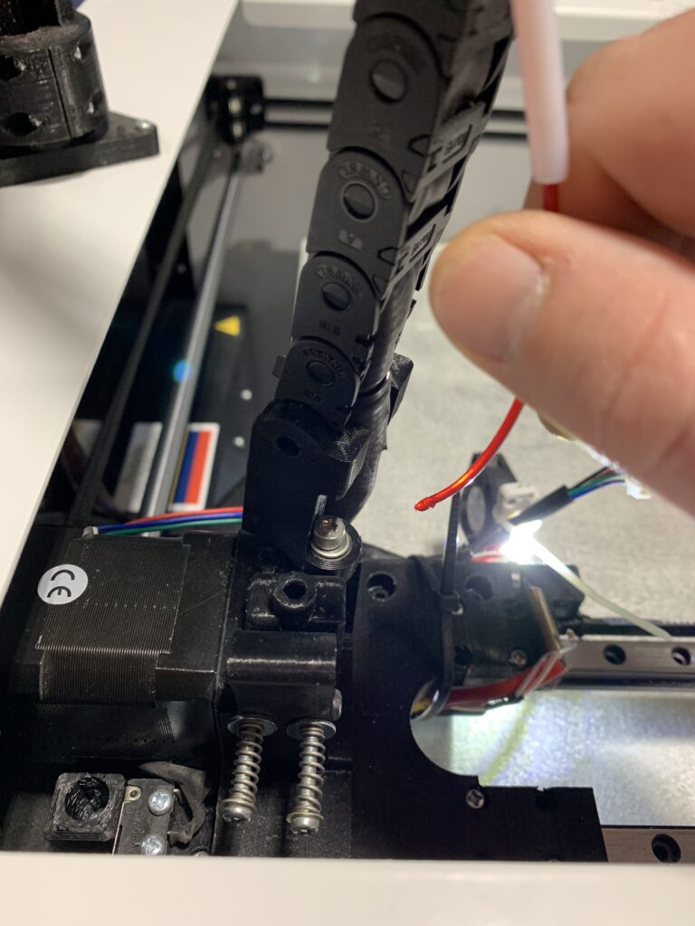
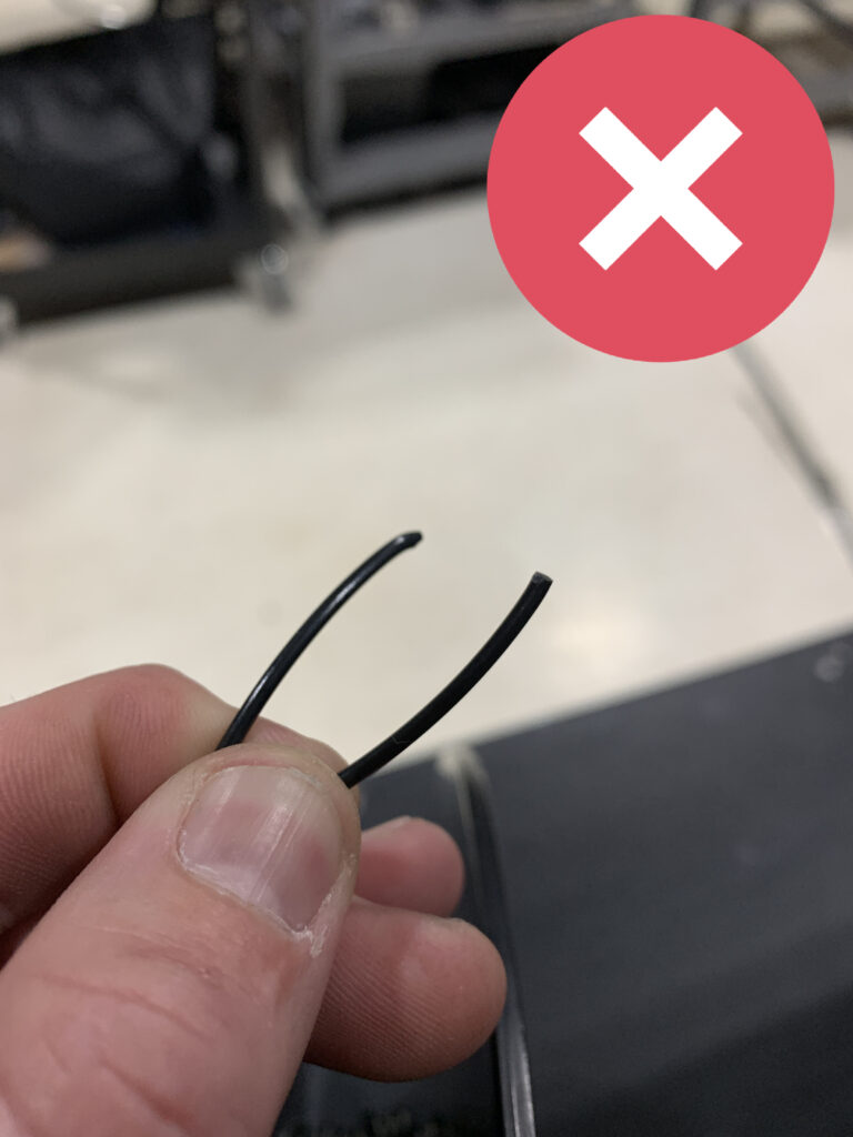
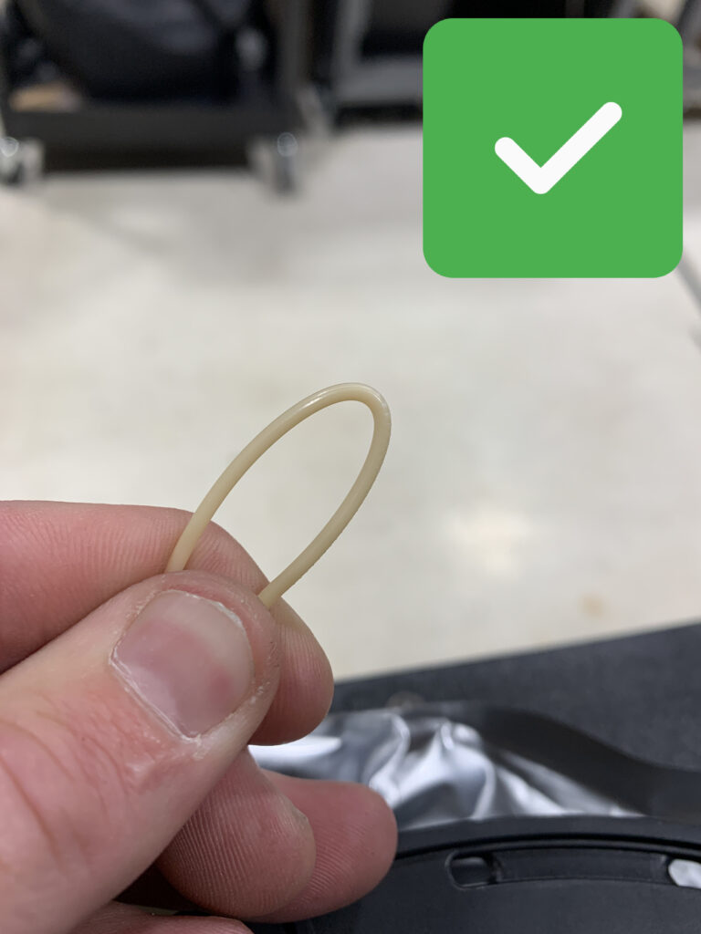
Remove Filament
Filament can become brittle when subjected to colder temperatures. It is good to remove the filament from the hot end AND extruder so it does not break inside.
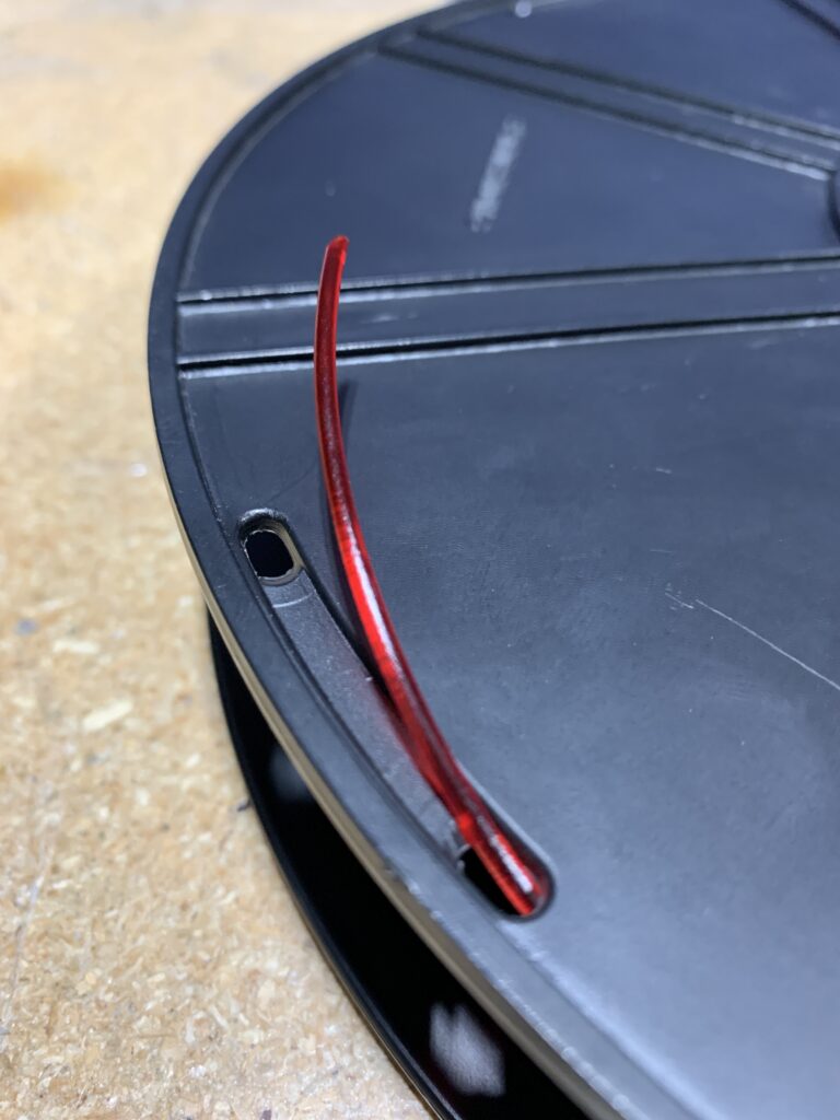
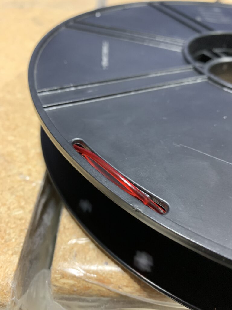
*Tip: Make sure to attach the end of the filament to the spool so it does not become entwined with itself. Some spools have some holes which you can insert the end of the filament into.
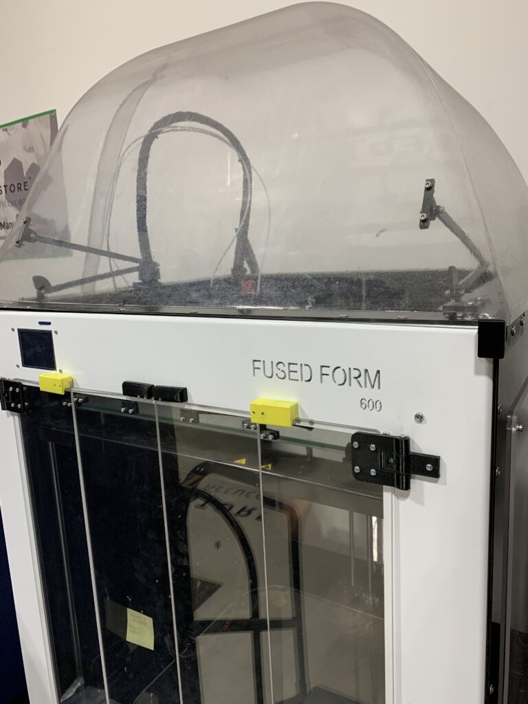
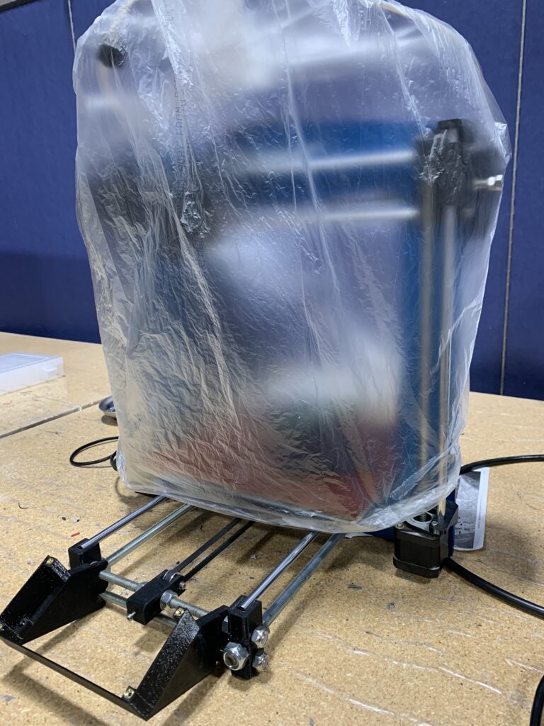
Cover the Printer
It is good to cover the printer if you do not plan on using it for a while. This prevents dust and particulates from getting on the guide rails, which will make the printer last longer and keep it quiet.
Home the Printer
It is good to home the printer before turning it off for an extended period of time. There should be an option to “home printer” or “home axis – all” within the printer’s interface. This will help prevent flat spots on guide rails and future problems.
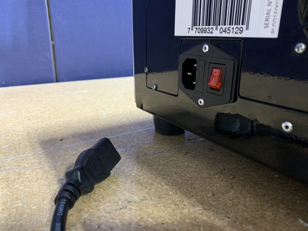
Unplug
Unplug the machine in case there is a powersurge. This will protect the mainboard and any other electrical components from electrical damage.
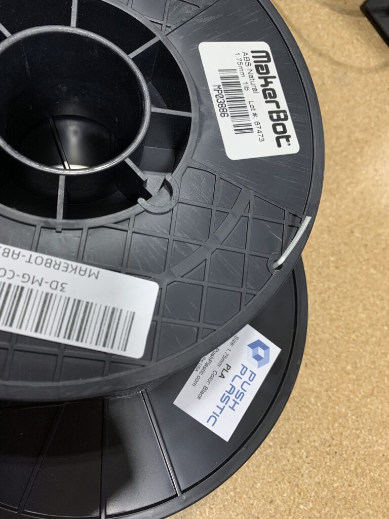
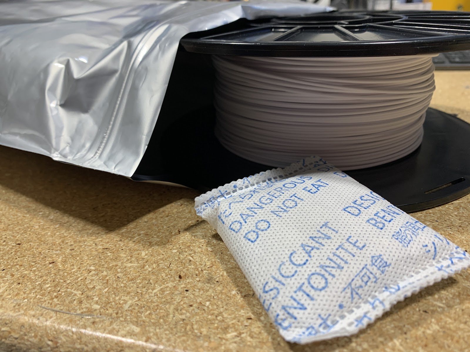
Storing Filament
It is important to store filament correctly. Failing to do so will result in filament expiring quickly. It is good to store filament in an airtight container such as a ziplock bag, mylar bag, or container of sorts. It is also recommended to store it with an apparatus that removes moisture from the air such as a silica-gel packet.
Contact us today for more on how to repair or maintain your printer.
"*" indicates required fields
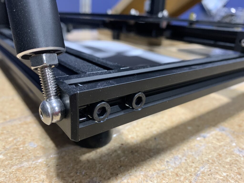
Tighten the screws on your printer
The screws that hold together the printer can come loose over time and through shipping. It’s good to go through the printer and tighten these every few months.
Level your printer bed
Beds can become unlevel after a certain amount of time. Glass beds are a popular choice and allow you to remove the bed to access the print. Signs that your bed is not level is the print not sticking to the bed, nozzle running into bed.
Different kinds of adhesive can be applied to beds to help with adhering. Some of these include: blue tape, hair spray, and a glue stick, amongst others. Check with the filament manufacturer to see what is best for the material.
Store your filament properly
Filament can expire over time. It’s best to store filament in a cool, dry location to ensure longevity of the material. Signs of bad filament are under extrusion, popping noise while it prints, and it doesn’t like to stick to the bed. Also, if the nozzle keeps clogging and breaks easily.
Clean your printer nozzle
Nozzles can clog after extended use. Signs of a clogged nozzle are that plastic is not coming out of the nozzle, prints are not sticking to the bed, filament curling when it exits the nozzle, and under extrusion.
Not every nozzle is compatible with every printer. Check with the manufacturer information to determine what type of nozzle you need.
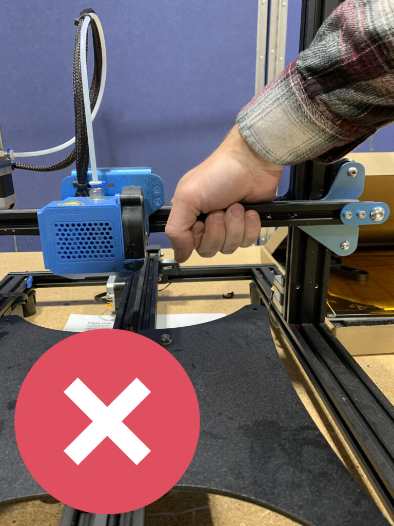
Don’t move the printer axis by hand
Moving the axes by hand is not recommended and can ruin the main board of the printer. If possible use the commands within the menus of your printer to move the axes.
If you need to move an axis by hand, power the printer off and remove the power cord and move the axis/ assembly slowly to desired location .
As always, The 3D Printing Store team is available to provide demonstrations, professional development courses, and educational courses to you and your team. Contact us or email arausch@the3dprintingstore.com for inquiries.
MakerBot is proud to now offer cloud-based 3D printing with the new My MakerBot. This in-browser platform connects your networked 3D printers, Thingiverse accounts, orders and support cases all in one place.
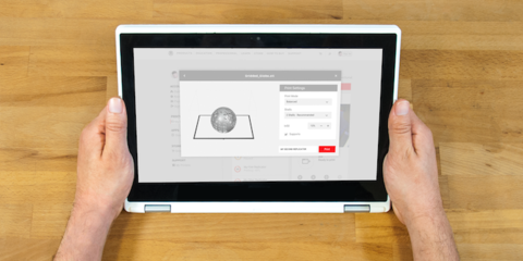
Upload and prepare files, print, then monitor their progress from any device, anywhere. An important new tool for schools, My MakerBot will broaden student access to 3D printers in Chromebook classrooms and makes it easier for educators to manage their use.
How to use My MakerBot
- Connect your MakerBot 3D printer via wifi or ethernet.
- Using MakerBot Print or the MakerBot Mobile app, add and authenticate your printer.
- Login to My MakerBot to see all of your authenticated printers.
- Upload an STL file, choose your settings, then print.
(Courtesy of Makerbot.com)